SPRADB7 September 2023 AM2431 , AM2432 , AM2434 , AM2631 , AM2631-Q1 , AM2632 , AM2632-Q1 , AM2634 , AM2634-Q1 , AM263P2-Q1 , AM263P4 , AM263P4-Q1 , AM2732 , AM2732-Q1
- 1
- Abstract
- Trademarks
- 1Introduction
- 2Thermal Resistance Overview
- 3Board Design Choices that Affect Thermal Performance
- 4Thermal Design Best Practices Review
- 5AM263x EVM Thermal Comparison with Data
- 6Using the Thermal Model
- 7References
2.3 Board Defined Thermal Resistances
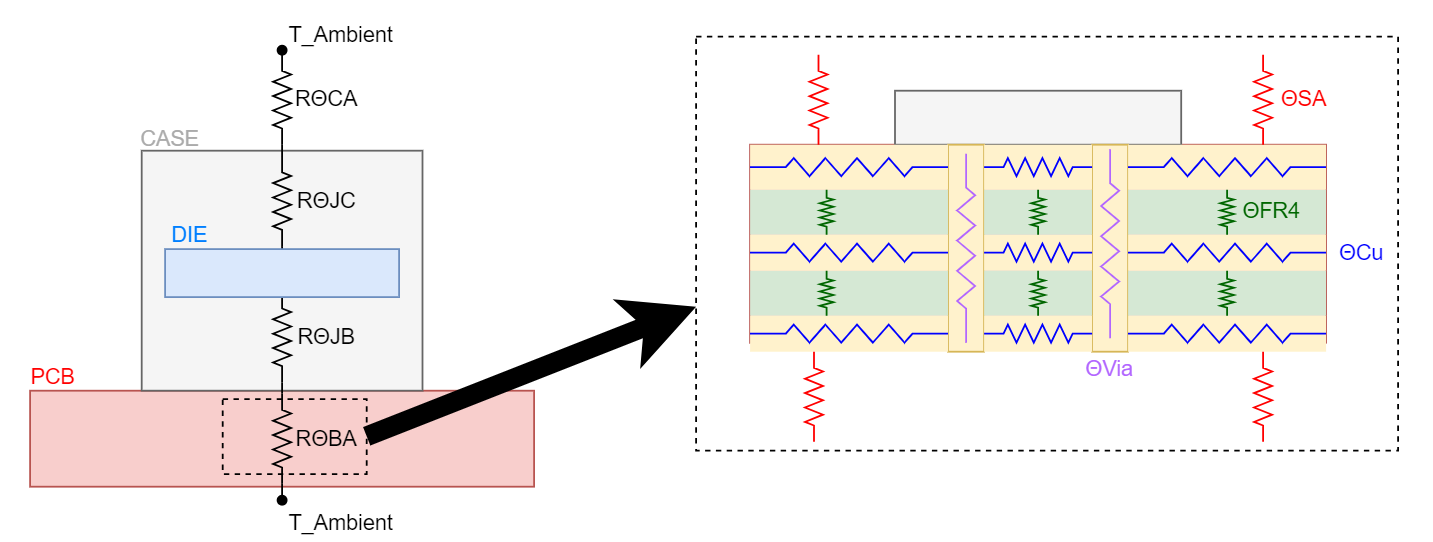
The design of a PCB will have a strong correlation to the difference between junction and ambient temperature. The ideal goal is for the junction temperature to be as close as possible to the ambient temperature but when the heat is not able to efficiently diffuse away from the SoC, then the delta between junction and ambient temperature will be larger. The thermal resistance between the board and ambient temperature can be broken up into four separate thermal resistances that will have varying values based on the system design:
- Thermal resistance of a thermal via (RΘVia)
- Thermal resistance of a copper plane (RΘCu)
- Thermal resistance of FR-4 Laminate (RΘFR-4)
- Thermal resistance of board surface area and ambient temperature (RΘSA)
 Figure 2-4 Breakdown of RΘBA
It is easy to imagine how some simple design choices can help with decreasing the RΘBA which subsequently decreases the RΘJA. A few examples of design choices to help with thermal performance are increasing copper volume of thermal vias, adding additional copper layers, or increasing board size. For a fullbreak down of design choices that affect thermal performance, refer to Section 3.