SWRA726 March 2022 CC1120 , CC1121 , CC1201 , CC1310 , CC1311P3 , CC1311R3 , CC1312PSIP , CC1312R , CC1312R7 , CC1314R10 , CC1350 , CC1352P , CC1352R , CC1354P10 , CC1354R10 , CC2340R5-Q1 , CC2640R2L , CC2651R3 , CC2652P , CC2652P7 , CC2652R , CC2652R7 , CC2652RB , CC2652RSIP , CC3130 , CC3135MOD , CC3230S , CC3235MODAS , CC3235MODASF , CC3235MODSF , CC3235S , WL1801MOD , WL1805MOD , WL1807MOD , WL1831 , WL1831MOD , WL1835MOD , WL1837MOD
- Trademarks
- 1Introduction
- 2Antenna Standing Wave Ratio (SWR) Measurement
- 3Evaluation Board Matching Components Location
- 4Volpert-Smith Chart
- 5868-MHz PCB Helix Antenna Measurement and Matching
- 62.4-GHz PCB Compact Antenna Measurement and Matching
- 7 2.4-GHz PCB Inverted-F Antenna Measurement and Matching
- 8Fast in-circuit or in-device Antenna Verification
- 9Conclusion
3 Evaluation Board Matching Components Location
In high frequency electronics, standard values of impedance are 50, 75, and 100 Ohm. Most manufacturers of test equipment, cables, connectors, and antennas use these values.
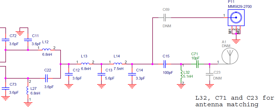
Transceiver data sheets or evaluation board schematics usually have a matching circuit for transforming a non-standard transceiver’s impedance to a standard value of 50 Ohm. Rarely, the antenna itself has an impedance value of 50 Ohm. That is why matching components for the antenna are usually on the board. For an example, view the evaluation board schematic for dual band CC1350 transceiver.
 Figure 3-1 Example of Matching
Network
Figure 3-1 Example of Matching
NetworkPassive components L32, C71, and C23 are for matching 868-MHz antenna impedance (Figure 3-1) to 50 Ohm. Values of 10 pF and 5.1 nH are for this specific antenna on the board. Values can be different for another type of antenna, circuit configuration, and components. Capacitor C15 (right pin) is inline with the 50 Ohm impedance value.
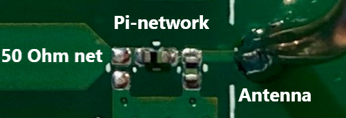
For Figure 2-7 and Figure 2-10, matching components exist (Z111-Z113). Figure 3-2 shows the zoomed in network. This matching network topology is also called the “Pi-network”, but passive components have “L-network” configuration. In addition, “T-network” type can be used.
 Figure 3-2 Zoomed in Matching
Network
Figure 3-2 Zoomed in Matching
NetworkTexas Instruments also manufactures modules, for example, Wi-Fi module WL1837MOD and CC3220MOD. These modules have 50 Ohm antenna connectors. WLAN antenna should have a 50 Ohm value to get proper SWR level, bandwidth, and communication range.