SNAA320B November 2019 – January 2024 LM4040-N , LM4050-N , LM4120 , LM4128 , LM4128-Q1 , LM4132 , LM4132-Q1 , REF102 , REF1925 , REF1930 , REF1933 , REF1941 , REF20-Q1 , REF200 , REF2025 , REF2030 , REF2033 , REF2041 , REF2125 , REF2912 , REF2920 , REF2925 , REF2930 , REF2933 , REF2940 , REF30 , REF3033-Q1 , REF31-Q1 , REF3112 , REF3120 , REF3125 , REF3130 , REF3133 , REF3140 , REF3212 , REF3212-EP , REF3220 , REF3220-EP , REF3225 , REF3225-EP , REF3230 , REF3230-EP , REF3233 , REF3240 , REF3312 , REF3318 , REF3320 , REF3325 , REF3330 , REF3333 , REF34-Q1 , REF3425 , REF3425-EP , REF3430 , REF3430-EP , REF3433 , REF3433-EP , REF3440 , REF3440-EP , REF3450 , REF35 , REF4132 , REF4132-Q1 , REF50 , REF5020-EP , REF5020A-Q1 , REF5025-EP , REF5025-HT , REF5025A-Q1 , REF5030A-Q1 , REF5040-EP , REF5040A-Q1 , REF5045A-Q1 , REF5050-EP , REF5050A-Q1 , REF50E , REF54 , REF6125 , REF6133 , REF6141 , REF6145 , REF6150 , REF6225 , REF6230 , REF6233 , REF6241 , REF6245 , REF6250 , REF70 , TL431LI , TL432LI , TLV431
6.4 Noise Example
When looking at noise in a signal chain, first see how the noise affects the dynamic performance of an ADC because SNR is one of the most important values when looking at AC and high frequency measurements which are common across many applications. The most common equation for SNR is shown in Equation 4 because this is the highest SNR level for a good N bit ADC.

To see the effect of the external voltage reference, look at the total noise at the ADC in Equation 5. The Total ADC noise (rms) is the combination of the uncorrelated noises from the ADC and voltage reference. Because the noises are uncorrelated, if we want the voltage reference to have a minimal impact on the SNR the VREF noise must be at least 5 times smaller than the ADC noise as shown in Equation 6.


In a voltage reference data sheet, noise is represented as flicker noise and wideband noise.
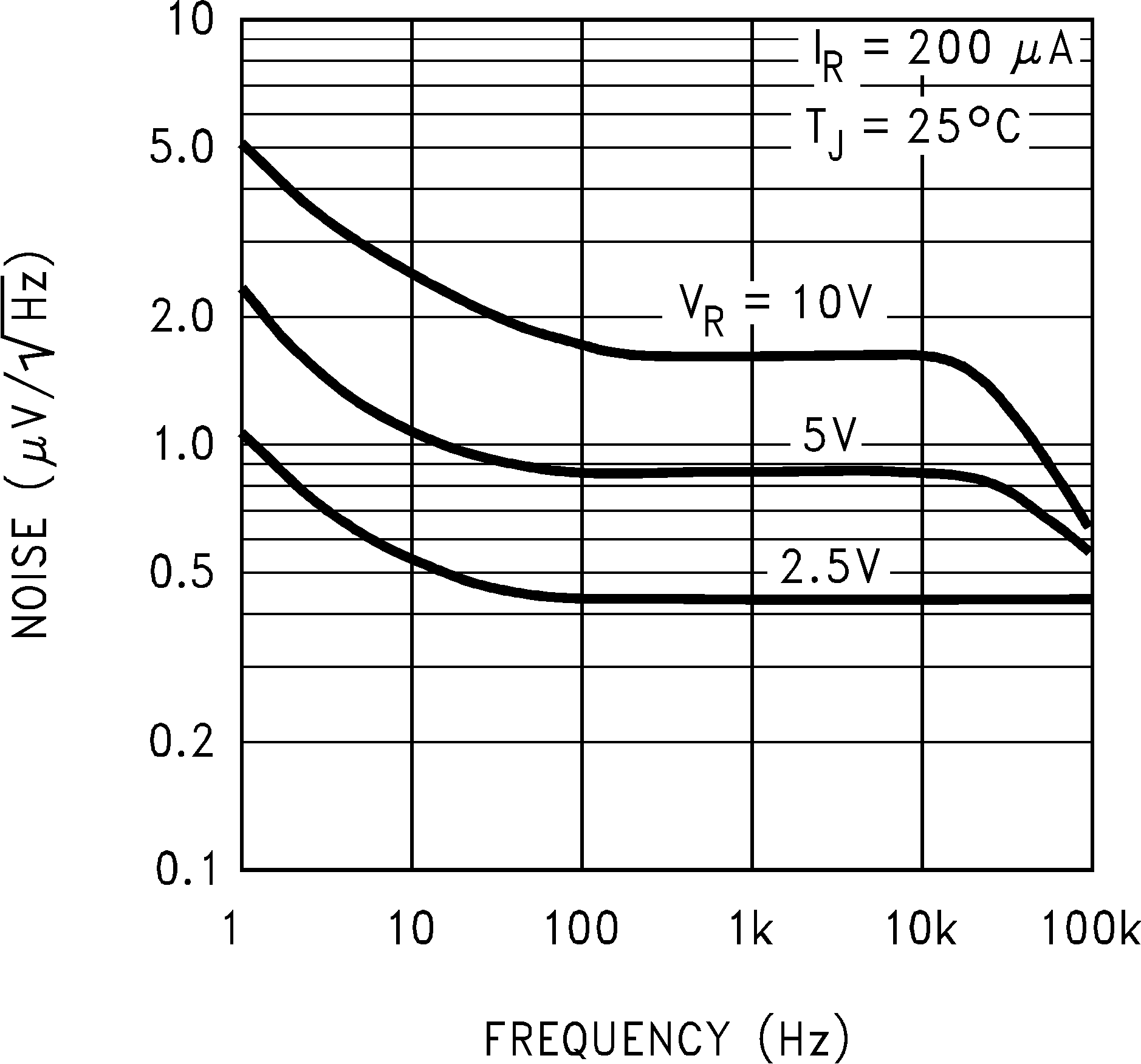
 Figure 6-1 LM4050 Noise Voltage Versus Frequency
In Figure 6-1 the frequency domain plot is given from 1Hz to the complete frequency range. In this plot the noise level k = 432nV/√(Hz) and a corner frequency Fc = 65Hz. Also the lower limit for flicker noise (FL) = 0.1Hz and the higher frequency limit (FH) is 10Hz. With this information the RMS flicker noise can be calculated as...

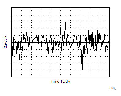
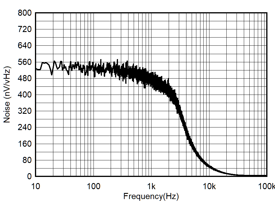
An alternative view of flicker noise is presented in Figure 6-2 and wideband noise is shown in Figure 6-3.
 Figure 6-2 REF3425 0.1Hz to 10Hz Noise
 Figure 6-3 REF3425 Noise Performance 10Hz to 100kHz
In this case flicker noise is calculated in Equation 8.

Flicker noise can’t be filtered out. Hence allowed wideband noise is calculated based on the ADC SNR requirement. Equation 9 shows how to find the wideband noise limit because the flicker noise cannot be filtered out.

If allowed wide band noise is more than total wide band noise of the reference than we need to filter out the extra wide band noise component. Equation 10 shows how to calculate the cut off frequency.
