SLVAE57B February 2021 – October 2021 LM5050-1 , LM5050-2 , LM5051 , LM66100 , LM74202-Q1 , LM74500-Q1 , LM74610-Q1 , LM74700-Q1 , LM74720-Q1 , LM74721-Q1 , LM74722-Q1 , LM7480-Q1 , LM7481-Q1 , LM76202-Q1 , SM74611 , TPS2410 , TPS2411 , TPS2412 , TPS2413 , TPS2419
- Trademarks
- 1 Introduction
- 2 Reverse Battery Protection
- 3 ORing Power Supplies
- 4 Reverse Battery Protection using MOSFETs
- 5 Reverse Polarity Protection vs Reverse Current Blocking
- 6 What is an Ideal Diode Controller?
- 7 Automotive Transient protection with Ideal Diode Controllers
- 8 ORing Power Supplies with Ideal Diode Controllers
- 9 Integrated Ideal Diode Solution
- 10Summary
- 11References
- 12Revision History
4.1 Reverse Battery Protection using P-Channel MOSFET
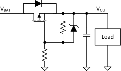
The schottky diode can be replaced with a P-Channel MOSFET to provide reverse battery protection as shown in Figure 4-1. The forward drop of the diode can be reduced by replacing the schottky diode with a P-channel MOSFET and its body diode oriented in the same direction as the schottky diode. During normal operation of the battery, the body diode from MOSFET is forward biased and conducts for a very short time until the MOSFET is turned ON when gate voltage is pulled below source. When the battery polarity is reversed, gate-source voltage swings positive and the MOSFET is turned off, protecting the downstream circuits from negative voltage.
 Figure 4-1 Reverse Battery Protection using P-Channel MOSFET
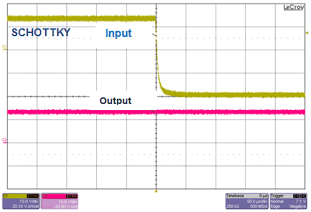
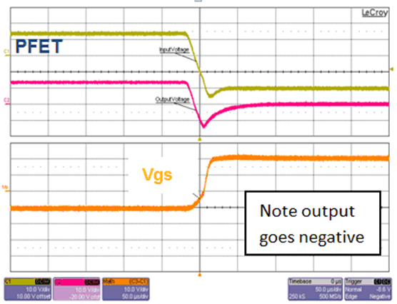
During dynamic reverse polarity where input quickly swings negative from positive, the P-Channel MOSFET is turned OFF when the input starts going negative because the gate-source voltage swings positive. Further note that the output also reaches close to or a diode drop lower than the system ground and protects the downstream DC/DC converters from negative voltage. The holdup capacitors are discharged as this P-Channel MOSFET protection does not block reverse current from flowing back into the input. An additional circuit can be added to sense the voltage difference between the input and output and turn off the MOSFET when the input goes lower than output, but requires increased cost and board space.
In Figure 4-3, the P-Channel MOSFET circuit protects the output from dynamic reverse polarity condition where the input quickly changes from 12 V to -20 V. Output remains protected from the negative voltage after the initial reverse voltage for 50 µs. Note that the output is completely discharged due to lack of reverse current blocking functionality and any hold up capacitors are discharged.
 Figure 4-2 Dynamic Reverse Polarity -
Schottky Diode
 Figure 4-3 Dynamic Reverse Polarity - P-Channel MOSFET