SLVAE57B February 2021 – October 2021 LM5050-1 , LM5050-2 , LM5051 , LM66100 , LM74202-Q1 , LM74500-Q1 , LM74610-Q1 , LM74700-Q1 , LM74720-Q1 , LM74721-Q1 , LM74722-Q1 , LM7480-Q1 , LM7481-Q1 , LM76202-Q1 , SM74611 , TPS2410 , TPS2411 , TPS2412 , TPS2413 , TPS2419
- Trademarks
- 1 Introduction
- 2 Reverse Battery Protection
- 3 ORing Power Supplies
- 4 Reverse Battery Protection using MOSFETs
- 5 Reverse Polarity Protection vs Reverse Current Blocking
- 6 What is an Ideal Diode Controller?
- 7 Automotive Transient protection with Ideal Diode Controllers
- 8 ORing Power Supplies with Ideal Diode Controllers
- 9 Integrated Ideal Diode Solution
- 10Summary
- 11References
- 12Revision History
7.3 Dynamic Reverse Polarity
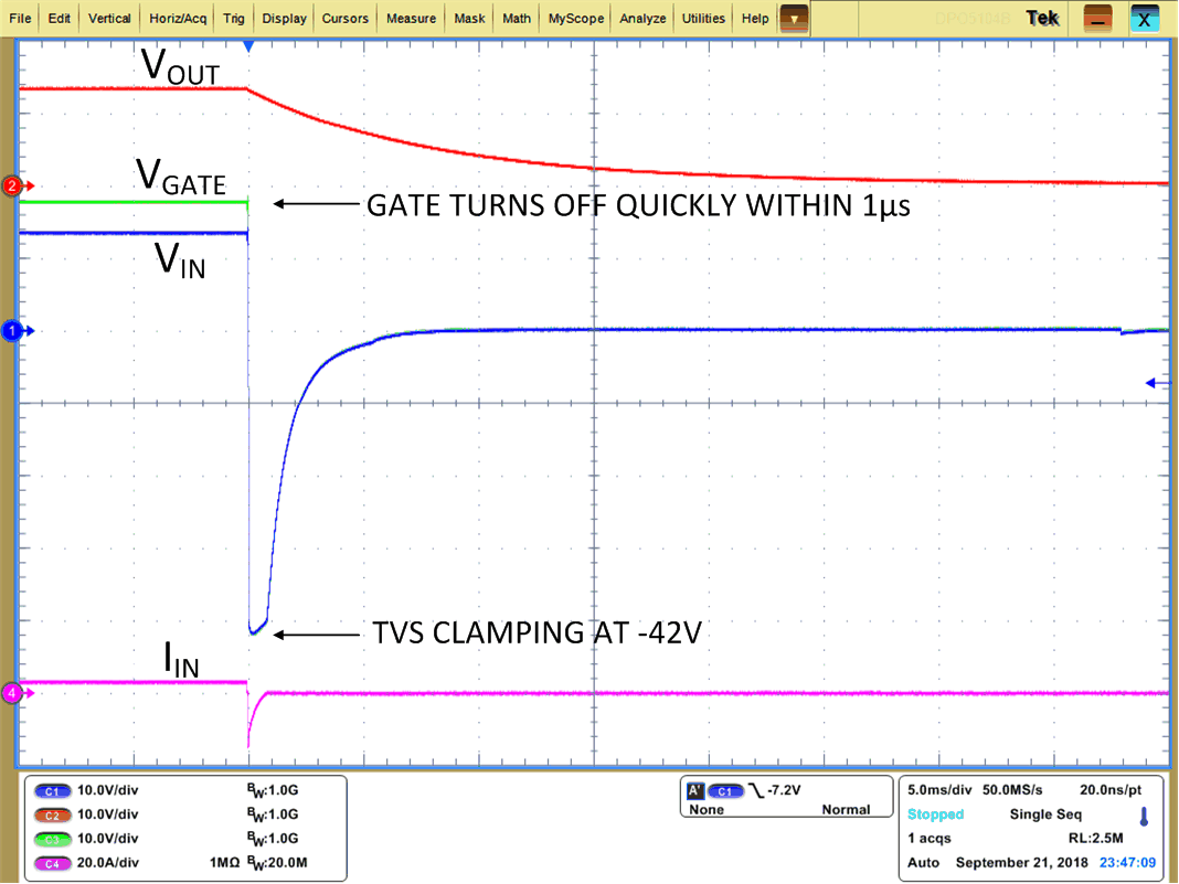
During dynamic reverse polarity conditions specified in ISO 7637-2 Pulse 1, negative transient voltage as low as -150 V is applied at the 12-V battery supply line with 10-Ω generator impedance for 2 ms and -600 V at the 24-V battery supply line with 50-Ω generator impedance for 1 ms. Figure 7-3 shows the response of the LM74700-Q1 to ISO 7637-2 Pulse 1 applied at the input. Before the test pulse is applied, the MOSFET is ON and allows the load current to pass through. When the ISO 7637-2 test pulse 1 is applied at the battery input, the load current starts to reverse quickly and tries to pull the output voltage negative. LM74700-Q1 detects the reverse current and turns OFF the MOSFET within 0.75 µs to block reverse current and prevents the output from going negative. Generally, bulk holdup capacitors are used after the ideal diode circuit provides energy to rest of the module during such transients. The LM74700-Q1 turns off the MOSFET quickly within 0.75 µs to prevent discharge of the bulk holdup capacitors. Note that the input TVS is required to clamp the voltage from exceeding the absolute maximum ratings of LM74700-Q1 and MOSFET.
 Figure 7-3 LM74700-Q1 Response to ISO 7637-2 Pulse 1