SLVAE57B February 2021 – October 2021 LM5050-1 , LM5050-2 , LM5051 , LM66100 , LM74202-Q1 , LM74500-Q1 , LM74610-Q1 , LM74700-Q1 , LM74720-Q1 , LM74721-Q1 , LM74722-Q1 , LM7480-Q1 , LM7481-Q1 , LM76202-Q1 , SM74611 , TPS2410 , TPS2411 , TPS2412 , TPS2413 , TPS2419
- Trademarks
- 1 Introduction
- 2 Reverse Battery Protection
- 3 ORing Power Supplies
- 4 Reverse Battery Protection using MOSFETs
- 5 Reverse Polarity Protection vs Reverse Current Blocking
- 6 What is an Ideal Diode Controller?
- 7 Automotive Transient protection with Ideal Diode Controllers
- 8 ORing Power Supplies with Ideal Diode Controllers
- 9 Integrated Ideal Diode Solution
- 10Summary
- 11References
- 12Revision History
6.5 Fast Load Transient Response
Ideal diode controllers operating with linear regulation control scheme maintain low forward voltage by controlling the gate-source voltage depending on load current. Gate-source voltage is lower at light load conditions and increases as the load current increases. While linear regulation scheme helps achieve zero DC reverse current, it can be disadvantageous to have low gate-source voltage during a sudden load transient from light load to heavy load. At lighter loads, gate-source voltage is operated just above Vth of MOSFET and the RDS(ON) is higher (than nominal) to meet to forward regulation, RDS(ON)_LIGHT_LOAD = 20 mV / ILIGHT_LOAD. When the load suddenly changes from light load to higher loads, the gate of the MOSFET needs to quickly charge from lower voltage to higher voltage to meet the sudden increased load demand. If the gate is not quickly charged, output voltage sees a worst case voltage drop equal to IHEAVY_LOAD × RDS(ON)_LIGHT_LOAD, but not more than MOSFETs body diode drop. In many ORing applications this droop in output voltage may not be acceptable as this reduces the headroom of power supply downstream.
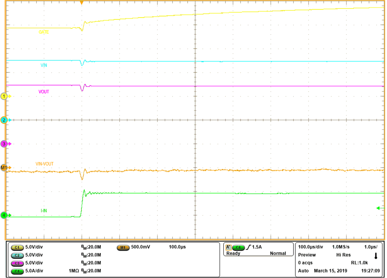
TI's ideal diode controller LM74700-Q1 features 11 mA peak source current when forward drop exceeds 50 mV. This feature helps in quickly charging the gate during fast load transient minimizing supply voltage droop. Figure 6-6 shows the load transient response of the LM74700-Q1 when load changes from 10 mA light load to 5 A suddenly. Output voltage drop is minimized to <50 mV as the controller quickly reacts and enhances the MOSFETs gate quickly.
 Figure 6-6 Fast Load Transient Response of LM74700-Q1