SLVAE57B February 2021 – October 2021 LM5050-1 , LM5050-2 , LM5051 , LM66100 , LM74202-Q1 , LM74500-Q1 , LM74610-Q1 , LM74700-Q1 , LM74720-Q1 , LM74721-Q1 , LM74722-Q1 , LM7480-Q1 , LM7481-Q1 , LM76202-Q1 , SM74611 , TPS2410 , TPS2411 , TPS2412 , TPS2413 , TPS2419
- Trademarks
- 1 Introduction
- 2 Reverse Battery Protection
- 3 ORing Power Supplies
- 4 Reverse Battery Protection using MOSFETs
- 5 Reverse Polarity Protection vs Reverse Current Blocking
- 6 What is an Ideal Diode Controller?
- 7 Automotive Transient protection with Ideal Diode Controllers
- 8 ORing Power Supplies with Ideal Diode Controllers
- 9 Integrated Ideal Diode Solution
- 10Summary
- 11References
- 12Revision History
4.3 Diode Rectification During Line Disturbance
In automotive systems, the battery line is subjected to various disturbances and transients during normal operation of the vehicle. One of the key tests is the supply line disturbance called AC superimposed test where AC disturbance with 2 V - 4 V peak to peak and 20 Hz to 30 KHz is applied on the battery supply line and the subsystems are expected to run without any functionality loss.
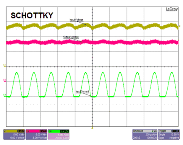
The schottky diode rectifies the AC line disturbance by blocking the reverse current. Figure 4-6 shows the rectified output and input current which has the AC component added due to the injected AC line disturbance. Power dissipation on the schottky diode increases due to the increased RMS current multiplied by the forward drop. This additional heat needs to be managed for reliable operation during the AC superimposed test.
 Figure 4-6 AC Superimposed Test -
Schottky Diode
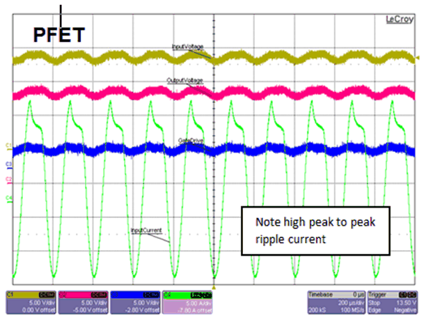
 Figure 4-7 AC Superimposed Test - P-Channel MOSFET
Figure 4-7 shows the performance of P-Channel MOSFET circuit. Since the P-Channel MOSFET does not block reverse current, rectification of the line disturbance does not happen and this results in increased RMS input current. Power dissipation on the MOSFET may not be a major concern due to the low forward voltage drop as the MOSFET remains on, however, the RMS current of output electrolytic capacitors due to its ESR produces additional heat on the capacitors. To prevent damage to the capacitors due to overheating, required capacitance can be split into multiple parallel capacitors to reduce the ESR. This adds to the system cost and space.
Rectification is possible by adding reverse current blocking functionality using an external comparator based methods, but this increases cost and space.