SLYY204C January 2021 – February 2024 AMC1300 , AMC1302 , AMC1302-Q1 , AMC1305M25-Q1 , AMC1311 , AMC1311-Q1 , AMC131M03-Q1 , AMC1336 , AMC1336-Q1 , AMC1350 , AMC1411 , AMC3301 , AMC3301-Q1 , AMC3330 , AMC3330-Q1 , AMC3336 , AMC3336-Q1 , ISOW1044 , ISOW1412 , ISOW7741 , ISOW7840 , ISOW7841 , ISOW7841A-Q1 , ISOW7842 , ISOW7843 , ISOW7844 , UCC12040 , UCC12041-Q1 , UCC12050 , UCC12051-Q1 , UCC14130-Q1 , UCC14131-Q1 , UCC14140-Q1 , UCC14141-Q1 , UCC14240-Q1 , UCC14241-Q1 , UCC14340-Q1 , UCC14341-Q1 , UCC15240-Q1 , UCC15241-Q1 , UCC21222-Q1 , UCC21530-Q1 , UCC21540 , UCC21710-Q1 , UCC21750-Q1 , UCC23513 , UCC25800-Q1 , UCC5870-Q1
What is galvanic isolation?
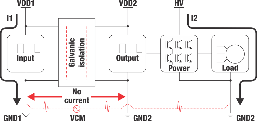
Galvanic isolation partitions an electrical system to prevent the flow of DC and undesirable AC between two parts, while still allowing signal and power transfer. Figure 1 illustrates two galvanically isolated circuits.
 Figure 1 Low- to high-voltage galvanic
signal isolation.
Figure 1 Low- to high-voltage galvanic
signal isolation.When GND1 is broken from GND2, I1 is galvanically isolated from I2. Since there is no commonality between GND1 and GND2, there is no common DC GND current shared through the isolation barrier. In addition to isolating shared GND connections and signal communication without conduction, it is also possible to use galvanic isolation for voltage-level shifting, since GND2 is transferable to a different floating potential relative to GND1.
High-voltage systems require additional isolation because more bidirectional signal information is communicated across the barrier. Figure 2 illustrates an example in which power, high-speed gate-driver signals and digital communication signals must all cross the isolation barrier. Many analog and digital circuits have specific bias voltage requirements where both digital signals and power cross the isolation barrier. An isolated high-resolution analog-to-digital converter (ADC) may require 3.3 V in the same system, whereas an isolated gate driver may require +15 V and –5 V. These requirements necessitate not just the transfer of signals across the isolation barrier but power as well.
 Figure 2 Types of signals transferring
across an isolation barrier.
Figure 2 Types of signals transferring
across an isolation barrier.Learn more about galvanic isolation in the What is Galvanic Isolation? video.