SPRACM9B June 2019 – November 2020 F29H850TU , F29H859TU-Q1 , TMS320F28384D , TMS320F28384S , TMS320F28386D , TMS320F28386S , TMS320F28388D , TMS320F28388S , TMS320F28P650DH , TMS320F28P650DK , TMS320F28P650SH , TMS320F28P650SK , TMS320F28P659DH-Q1 , TMS320F28P659DK-Q1 , TMS320F28P659SH-Q1
- Trademarks
- 1 Introduction
- 2 Benefits of the TMS320F2838x MCU for High-Bandwidth Current Loop
- 3 Current Loops in Servo Drives
- 4 Outline of the Fast Current Loop Library
- 5 Fast Current Loop Evaluation
- 6 Incremental Build Level 1
- 7 Incremental Build Level 2
- 8 Incremental Build Level 3
- 9 Incremental Build Level 4
- 10Incremental Build Level 5
- 11Incremental Build Level 6
- 12Incremental Build Level 7
- 13Incremental Build Level 8
- 14References
- 15Revision History
12.6 Running the Application
This section deals with running the application.
- Verify or restore the connections if disconnected before.
- Reload CPU1 and CM applications
- Run CPU1 first and hand-off the EtherCAT peripheral to CM
- Run the CM next to setup the EtherCAT connection with master and IPC link with CPU1
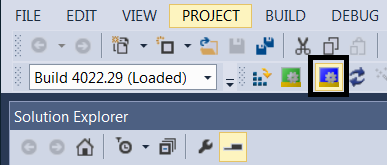
- From TwinCAT window, rescan for devices, and restart TwinCAT in config mode.
 Figure 12-5 TwinCAT Restart in Config Mode Icon
 - ECAT messages can be viewed as variables in CCS debug window. If not done already, right-click within the CCS Expressions window and choose Import. Then browse to and select fcl_f2838x_tmdxiddk_ecat_vars.txt file from the debug directory. Variables 'countMainLoop', 'dataBufferFromCM' and 'dataBuffertoCM' are used by C28x core only while 'ipcCMToCPUDataBuffer' and 'ipcCPUToCMDataBuffer' are used by both C28 and CM cores and hence can be viewed from both 'Debug' spaces.
- Within TwinCAT, double-click on the discovered EtherCAT box and observe that the EtherCAT slave is running in OP mode.
 Figure 12-6 EtherCAT Slave in OP Mode
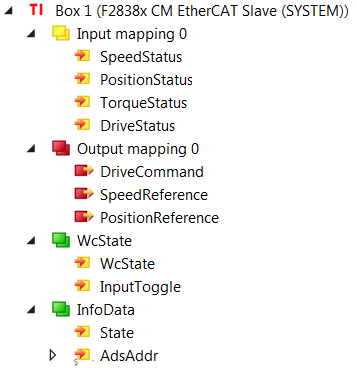
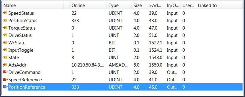
 - Within TwinCAT, expand the explorer to the EtherCAT box (I/O --> Devices -->Device 2 (EtherCAT) --> Box 1 (F2838x CM EtherCAT Slave(SYSTEM))) and find the various output/input mappings as shown in Figure 12-7. Double click on Box1 to get the F2838x CM slave input /output data window as shown in Figure 12-8.
- Select Input mapping 0 to view all the status feedback from the drive. The following are the drive parameters monitored through EtherCAT:
- SpeedStatus
- PositionStatus
- TorqueStatus
- DriveStatus
- Select Output mapping 0 to view and enter all the commands to the drive:
- DriveCommand
- SpeedReference
- PositionReference
 Figure 12-7 TwinCAT Solution Explorer Inputs and Outputs
 Figure 12-8 F2838x CM EtherCAT Slave (SYSTEM) Input/Output Data
 - Select Input mapping 0 to view all the status feedback from the drive. The following are the drive parameters monitored through EtherCAT:
- This build level is a loop back example to verify the EtherCAT functionality. So, if the command data entered in a certain output mapping variable is returned back in a certain input mapping variable, it confirms the functionality of EtherCAT slave on the F2838x. The loop back association is as follows:
- SpeedReference --> SpeedStatus
- PositionReference --> PositionStatus
- DriveCommand --> DriveStatus