SPRACN0F October   2021  – March 2023 TMS320F280021 , TMS320F280021-Q1 , TMS320F280023 , TMS320F280023-Q1 , TMS320F280023C , TMS320F280025 , TMS320F280025-Q1 , TMS320F280025C , TMS320F280025C-Q1 , TMS320F280033 , TMS320F280034 , TMS320F280034-Q1 , TMS320F280036-Q1 , TMS320F280036C-Q1 , TMS320F280037 , TMS320F280037-Q1 , TMS320F280037C , TMS320F280037C-Q1 , TMS320F280038-Q1 , TMS320F280038C-Q1 , TMS320F280039 , TMS320F280039-Q1 , TMS320F280039C , TMS320F280039C-Q1 , TMS320F280040-Q1 , TMS320F280040C-Q1 , TMS320F280041 , TMS320F280041-Q1 , TMS320F280041C , TMS320F280041C-Q1 , TMS320F280045 , TMS320F280048-Q1 , TMS320F280048C-Q1 , TMS320F280049 , TMS320F280049-Q1 , TMS320F280049C , TMS320F280049C-Q1 , TMS320F28374D , TMS320F28374S , TMS320F28375D , TMS320F28375S , TMS320F28375S-Q1 , TMS320F28376D , TMS320F28376S , TMS320F28377S , TMS320F28377S-Q1 , TMS320F28378D , TMS320F28378S , TMS320F28379D , TMS320F28379D-Q1 , TMS320F28379S , TMS320F28384D , TMS320F28384S , TMS320F28386D , TMS320F28386S , TMS320F28388D , TMS320F28388S , TMS320F28P650DH , TMS320F28P650DK , TMS320F28P650SH , TMS320F28P650SK , TMS320F28P659DK-Q1


  1.    The Essential Guide for Developing With C2000™ Real-Time Microcontrollers
  2.   Trademarks
  3. 1C2000 and Real-Time Control
    1. 1.1 Getting Started Resources
    2. 1.2 Processing
    3. 1.3 Control
    4. 1.4 Sensing
    5. 1.5 Interface
    6. 1.6 Functional Safety
  4. 2Sensing Key Technologies
    1. 2.1 Accurate Digital Domain Representation of Analog Signals
      1. 2.1.1 Value Proposition
      2. 2.1.2 In Depth
      3. 2.1.3 Device List
      4. 2.1.4 Hardware Platforms and Software Examples
      5. 2.1.5 Documentation
    2. 2.2 Optimizing Acquisition Time vs Circuit Complexity for Analog Inputs
      1. 2.2.1 Value Proposition
      2. 2.2.2 In Depth
      3. 2.2.3 Device List
      4. 2.2.4 Hardware Platforms and Software Examples
      5. 2.2.5 Documentation
    3. 2.3 Hardware Based Monitoring of Dual-Thresholds Using a Single Pin Reference
      1. 2.3.1 Value Proposition
      2. 2.3.2 In Depth
      3. 2.3.3 Device List
      4. 2.3.4 Hardware Platforms and Software Examples
      5. 2.3.5 Documentation
    4. 2.4 Resolving Tolerance and Aging Effects During ADC Sampling
      1. 2.4.1 Value Proposition
      2. 2.4.2 In Depth
      3. 2.4.3 Device List
      4. 2.4.4 Hardware Platforms and Software Examples
      5. 2.4.5 Documentation
    5. 2.5 Realizing Rotary Sensing Solutions Using C2000 Configurable Logic Block
      1. 2.5.1 Value Proposition
      2. 2.5.2 In Depth
      3. 2.5.3 Device List
      4. 2.5.4 Hardware Platforms and Software Examples
      5. 2.5.5 Documentation
    6. 2.6 Smart Sensing Across An Isolation Boundary
      1. 2.6.1 Value Proposition
      2. 2.6.2 In Depth
      3. 2.6.3 Device List
      4. 2.6.4 Hardware Platforms and Software Examples
      5. 2.6.5 Documentation
    7. 2.7 Enabling Intra-Period Updates in High Bandwidth Control Topologies
      1. 2.7.1 Value Proposition
      2. 2.7.2 In Depth
      3. 2.7.3 Device List
      4. 2.7.4 Hardware Platforms and Software Examples
      5. 2.7.5 Documentation
    8. 2.8 Accurate Monitoring of Real-Time Control System Events Without the Need for Signal Conditioning
      1. 2.8.1 Value Proposition
      2. 2.8.2 In Depth
      3. 2.8.3 Device List
      4. 2.8.4 Hardware Platforms and Software Examples
      5. 2.8.5 Documentation
  5. 3Processing Key Technologies
    1. 3.1 Accelerated Trigonometric Math Functions
      1. 3.1.1 Value Proposition
      2. 3.1.2 In Depth
      3. 3.1.3 Device List
      4. 3.1.4 Hardware Platforms and Software Examples
      5. 3.1.5 Documentation
    2. 3.2 Fast Onboard Integer Division
      1. 3.2.1 Value Proposition
      2. 3.2.2 In Depth
      3. 3.2.3 Device List
      4. 3.2.4 Hardware Platforms and Software Platforms
      5. 3.2.5 Documentation
    3. 3.3 Hardware Support for Double-Precision Floating-Point Operations
      1. 3.3.1 Value Proposition
      2. 3.3.2 In Depth
      3. 3.3.3 Device List
      4. 3.3.4 Hardware Platforms and Software Examples
      5. 3.3.5 Documentation
    4. 3.4 Increasing Control Loop Bandwidth With An Independent Processing Unit
      1. 3.4.1 Value Proposition
      2. 3.4.2 In Depth
      3. 3.4.3 Device List
      4. 3.4.4 Hardware Platforms and Software Examples
      5. 3.4.5 Documentation
    5. 3.5 Flexible System Interconnect: C2000 X-Bar
      1. 3.5.1 Value Proposition
      2. 3.5.2 In Depth
      3. 3.5.3 Device List
      4. 3.5.4 Hardware Platforms and Software Examples
      5. 3.5.5 Documentation
    6. 3.6 Improving Control Performance With Nonlinear PID Control
      1. 3.6.1 Value Proposition
      2. 3.6.2 In Depth
      3. 3.6.3 Device List
      4. 3.6.4 Hardware Platforms and Software Examples
      5. 3.6.5 Documentation
    7. 3.7 Understanding Flash Memory Performance In Real-Time Control Applications
      1. 3.7.1 Value Proposition
      2. 3.7.2 In Depth
      3. 3.7.3 Device List
      4. 3.7.4 Hardware Platforms and Software Examples
      5. 3.7.5 Documentation
    8. 3.8 Deterministic Program Execution With the C28x DSP Core
      1. 3.8.1 Value Proposition
      2. 3.8.2 In Depth
      3. 3.8.3 Device List
      4. 3.8.4 Hardware Platforms and Software Examples
      5. 3.8.5 Documentation
    9. 3.9 Efficient Live Firmware Updates (LFU) and Firmware Over-The-Air (FOTA) updates
      1. 3.9.1 Value Proposition
      2. 3.9.2 In Depth
      3. 3.9.3 Device List
      4. 3.9.4 Hardware Platforms and Software Examples
      5. 3.9.5 Documentation
  6. 4Control Key Technologies
    1. 4.1 Reducing Limit Cycling in Control Systems With C2000 HRPWMs
      1. 4.1.1 Value Proposition
      2. 4.1.2 In Depth
      3. 4.1.3 Device List
      4. 4.1.4 Hardware Platforms and Software Examples
      5. 4.1.5 Documentation
    2. 4.2 Shoot Through Prevention for Current Control Topologies With Configurable Deadband
      1. 4.2.1 Value Proposition
      2. 4.2.2 In Depth
      3. 4.2.3 Device List
      4. 4.2.4 Documentation
    3. 4.3 On-Chip Hardware Customization Using the C2000 Configurable Logic Block
      1. 4.3.1 Value Proposition
      2. 4.3.2 In Depth
      3. 4.3.3 Device List
      4. 4.3.4 Hardware Platforms and Software Examples
      5. 4.3.5 Documentation
    4. 4.4 Fast Detection of Over and Under Currents and Voltages
      1. 4.4.1 Value Proposition
      2. 4.4.2 In Depth
      3. 4.4.3 Device List
      4. 4.4.4 Hardware Platforms and Software Examples
      5. 4.4.5 Documentation
    5. 4.5 Improving System Power Density With High Resolution Phase Control
      1. 4.5.1 Value Proposition
      2. 4.5.2 In Depth
      3. 4.5.3 Device List
      4. 4.5.4 Hardware Platforms and Software Examples
      5. 4.5.5 Documentation
    6. 4.6 Safe and Optimized PWM Updates in High-Frequency, Multi-Phase and Variable Frequency Topologies
      1. 4.6.1 Value Proposition
      2. 4.6.2 In Depth
      3. 4.6.3 Device List
      4. 4.6.4 Hardware Platforms and Software Examples
      5. 4.6.5 Documentation
    7. 4.7 Solving Event Synchronization Across Multiple Controllers in Decentralized Control Systems
      1. 4.7.1 Value Proposition
      2. 4.7.2 In Depth
      3. 4.7.3 Device List
      4. 4.7.4 Hardware Platforms and Software Examples
      5. 4.7.5 Documentation
  7. 5Interface Key Technologies
    1. 5.1 Direct Host Control of C2000 Peripherals
      1. 5.1.1 Value Proposition
      2. 5.1.2 In Depth
        1. 5.1.2.1 HIC Bridge for FSI Applications
        2. 5.1.2.2 HIC Bridge for Position Encoder Applications Using CLB
      3. 5.1.3 Device List
      4. 5.1.4 Hardware Platforms and Software Examples
      5. 5.1.5 Documentation
    2. 5.2 Securing External Communications and Firmware Updates With an AES Engine
      1. 5.2.1 Value Proposition
      2. 5.2.2 In Depth
      3. 5.2.3 Device List
      4. 5.2.4 Hardware Platforms and Software Examples
      5. 5.2.5 Documentation
    3. 5.3 Distributed Real-Time Control Across an Isolation Boundary
      1. 5.3.1 Value Proposition
      2. 5.3.2 In Depth
      3. 5.3.3 Device List
      4. 5.3.4 Hardware Platforms and Software Examples
      5. 5.3.5 Documentation
    4. 5.4 Custom Tests and Data Pattern Generation Using the Embedded Pattern Generator (EPG)
      1. 5.4.1 Value Proposition
      2. 5.4.2 In Depth
      3. 5.4.3 Device List
      4. 5.4.4 Hardware Platforms and Software Examples
      5. 5.4.5 Documentation
  8. 6Safety Key Technologies
    1. 6.1 Non-Intrusive Run Time Monitoring and Diagnostics as Part of the Control Loop
      1. 6.1.1 Value Proposition
      2. 6.1.2 In Depth
      3. 6.1.3 Device List
      4. 6.1.4 Hardware Platforms and Software Examples
      5. 6.1.5 Documentation
    2. 6.2 Hardware Built-In Self-Test of the C28x CPU
      1. 6.2.1 Value Proposition
      2. 6.2.2 In Depth
      3. 6.2.3 Device List
      4. 6.2.4 Hardware Platforms and Software Examples
      5. 6.2.5 Documentation
    3. 6.3 Zero CPU Overhead Cyclic Redundancy Check for Embedded On-Chip Memories
      1. 6.3.1 Value Proposition
      2. 6.3.2 In Depth
      3. 6.3.3 Device List
      4. 6.3.4 Hardware Platforms and Software Examples
      5. 6.3.5 Documentation
    4. 6.4 Boot Code Authentication Prior To Code Execution
      1. 6.4.1 Value Proposition
      2. 6.4.2 In Depth
      3. 6.4.3 Device List
      4. 6.4.4 Hardware Platforms and Software Examples
        1. 6.4.4.1 Documentation
  9. 7References
    1. 7.1 Device List
    2. 7.2 Hardware/Software Resources
    3. 7.3 Documentation
  10. 8Revision History

In Depth

Fault detection and reaction is important in most systems, not only for avoiding an undefined output, but for preventing damage to components both on and off the main Printed Circuit Board (PCB). The speed at which the fault detection takes place, as well as the final FET output state change, is critical to the system. A dedicated subsystem that ties together the analog and digital domains has been implemented on the C2000 MCU for handling this requirement: the Comparator Subsystem or CMPSS (#T5843526-91).
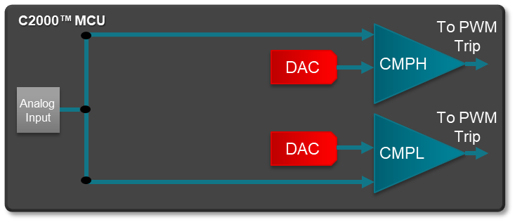
GUID-241B5089-DB14-4C0A-9BE3-FEF9CCBCAAFC-low.png Figure 4-6 CMPSS Visualization

There are up to eight CMPSS modules on each C2000 MCU, with internal DACs that give the inverting/comparison detection level for the line that is being monitored. As shown in #T5843526-91, each CMPSS module has two comparators for simultaneous high and low detection. Using the CMPSS has several advantages over using the ADC for fault detection:

  • System Overhead: Using the CMPSS to monitor a pin is an essentially zero overhead operation after the initial setup. The pin is always monitored against the comparison value until disabled. Other techniques would require periodic ADC conversions and threshold checking.
  • Latency: While the ADC sampling rate can be simply factored into the period of the control loop, there is not a deterministic constant to a fault condition. As such there will be an inherent delay to detect the fail, both from a point of sample to the conversion time of the ADC itself. The comparator has no such trigger requirement or sample time, it is continuously monitoring the analog signal.
  • Dedicated PWM Trip Zone input: The output of every CMPSS module can be tied directly into the Trip Zone of any PWM, and the action when the signal is received is configurable in software. This means there is no software overhead as there would be in processing an ADC ISR to then create the action to the PWM in software.
  • No clock dependence: Since by definition a comparator is a purely analog domain circuit there are not clock dependencies to the changing state of its output based on the input. The C2000 MCU has carried this forward to give a asynchronous path from the comparator to the PWM. This allows for the fastest possible time from fault detection to pin state change, in addition to removing any clock dependence (Table 4-2).
    Table 4-2 Comparison of Fault Detection and Trip Methods
    Sampling Method Sample Time (min) Result Ready (min) Latch and Change PWM Pin (@200 MHz SysClk) Total Time From Fault To Trip
    12-bit ADC 75 ns 260 ns approximately 100 ns(inc ISR) 435 ns
    12-bit ADC w/PPB 75 ns 260 ns 10 ns 355 ns
    CMPSS NA NA NA 60 ns
  • Simultaneous high and low detection: Each input to a CMPSS module routes the signal to two physically independent comparators that give the ability to detect both overshoot and undershoot at the same time.