SPRACN0F October   2021  – March 2023 TMS320F280021 , TMS320F280021-Q1 , TMS320F280023 , TMS320F280023-Q1 , TMS320F280023C , TMS320F280025 , TMS320F280025-Q1 , TMS320F280025C , TMS320F280025C-Q1 , TMS320F280033 , TMS320F280034 , TMS320F280034-Q1 , TMS320F280036-Q1 , TMS320F280036C-Q1 , TMS320F280037 , TMS320F280037-Q1 , TMS320F280037C , TMS320F280037C-Q1 , TMS320F280038-Q1 , TMS320F280038C-Q1 , TMS320F280039 , TMS320F280039-Q1 , TMS320F280039C , TMS320F280039C-Q1 , TMS320F280040-Q1 , TMS320F280040C-Q1 , TMS320F280041 , TMS320F280041-Q1 , TMS320F280041C , TMS320F280041C-Q1 , TMS320F280045 , TMS320F280048-Q1 , TMS320F280048C-Q1 , TMS320F280049 , TMS320F280049-Q1 , TMS320F280049C , TMS320F280049C-Q1 , TMS320F28374D , TMS320F28374S , TMS320F28375D , TMS320F28375S , TMS320F28375S-Q1 , TMS320F28376D , TMS320F28376S , TMS320F28377S , TMS320F28377S-Q1 , TMS320F28378D , TMS320F28378S , TMS320F28379D , TMS320F28379D-Q1 , TMS320F28379S , TMS320F28384D , TMS320F28384S , TMS320F28386D , TMS320F28386S , TMS320F28388D , TMS320F28388S , TMS320F28P650DH , TMS320F28P650DK , TMS320F28P650SH , TMS320F28P650SK , TMS320F28P659DK-Q1


  1.    The Essential Guide for Developing With C2000™ Real-Time Microcontrollers
  2.   Trademarks
  3. 1C2000 and Real-Time Control
    1. 1.1 Getting Started Resources
    2. 1.2 Processing
    3. 1.3 Control
    4. 1.4 Sensing
    5. 1.5 Interface
    6. 1.6 Functional Safety
  4. 2Sensing Key Technologies
    1. 2.1 Accurate Digital Domain Representation of Analog Signals
      1. 2.1.1 Value Proposition
      2. 2.1.2 In Depth
      3. 2.1.3 Device List
      4. 2.1.4 Hardware Platforms and Software Examples
      5. 2.1.5 Documentation
    2. 2.2 Optimizing Acquisition Time vs Circuit Complexity for Analog Inputs
      1. 2.2.1 Value Proposition
      2. 2.2.2 In Depth
      3. 2.2.3 Device List
      4. 2.2.4 Hardware Platforms and Software Examples
      5. 2.2.5 Documentation
    3. 2.3 Hardware Based Monitoring of Dual-Thresholds Using a Single Pin Reference
      1. 2.3.1 Value Proposition
      2. 2.3.2 In Depth
      3. 2.3.3 Device List
      4. 2.3.4 Hardware Platforms and Software Examples
      5. 2.3.5 Documentation
    4. 2.4 Resolving Tolerance and Aging Effects During ADC Sampling
      1. 2.4.1 Value Proposition
      2. 2.4.2 In Depth
      3. 2.4.3 Device List
      4. 2.4.4 Hardware Platforms and Software Examples
      5. 2.4.5 Documentation
    5. 2.5 Realizing Rotary Sensing Solutions Using C2000 Configurable Logic Block
      1. 2.5.1 Value Proposition
      2. 2.5.2 In Depth
      3. 2.5.3 Device List
      4. 2.5.4 Hardware Platforms and Software Examples
      5. 2.5.5 Documentation
    6. 2.6 Smart Sensing Across An Isolation Boundary
      1. 2.6.1 Value Proposition
      2. 2.6.2 In Depth
      3. 2.6.3 Device List
      4. 2.6.4 Hardware Platforms and Software Examples
      5. 2.6.5 Documentation
    7. 2.7 Enabling Intra-Period Updates in High Bandwidth Control Topologies
      1. 2.7.1 Value Proposition
      2. 2.7.2 In Depth
      3. 2.7.3 Device List
      4. 2.7.4 Hardware Platforms and Software Examples
      5. 2.7.5 Documentation
    8. 2.8 Accurate Monitoring of Real-Time Control System Events Without the Need for Signal Conditioning
      1. 2.8.1 Value Proposition
      2. 2.8.2 In Depth
      3. 2.8.3 Device List
      4. 2.8.4 Hardware Platforms and Software Examples
      5. 2.8.5 Documentation
  5. 3Processing Key Technologies
    1. 3.1 Accelerated Trigonometric Math Functions
      1. 3.1.1 Value Proposition
      2. 3.1.2 In Depth
      3. 3.1.3 Device List
      4. 3.1.4 Hardware Platforms and Software Examples
      5. 3.1.5 Documentation
    2. 3.2 Fast Onboard Integer Division
      1. 3.2.1 Value Proposition
      2. 3.2.2 In Depth
      3. 3.2.3 Device List
      4. 3.2.4 Hardware Platforms and Software Platforms
      5. 3.2.5 Documentation
    3. 3.3 Hardware Support for Double-Precision Floating-Point Operations
      1. 3.3.1 Value Proposition
      2. 3.3.2 In Depth
      3. 3.3.3 Device List
      4. 3.3.4 Hardware Platforms and Software Examples
      5. 3.3.5 Documentation
    4. 3.4 Increasing Control Loop Bandwidth With An Independent Processing Unit
      1. 3.4.1 Value Proposition
      2. 3.4.2 In Depth
      3. 3.4.3 Device List
      4. 3.4.4 Hardware Platforms and Software Examples
      5. 3.4.5 Documentation
    5. 3.5 Flexible System Interconnect: C2000 X-Bar
      1. 3.5.1 Value Proposition
      2. 3.5.2 In Depth
      3. 3.5.3 Device List
      4. 3.5.4 Hardware Platforms and Software Examples
      5. 3.5.5 Documentation
    6. 3.6 Improving Control Performance With Nonlinear PID Control
      1. 3.6.1 Value Proposition
      2. 3.6.2 In Depth
      3. 3.6.3 Device List
      4. 3.6.4 Hardware Platforms and Software Examples
      5. 3.6.5 Documentation
    7. 3.7 Understanding Flash Memory Performance In Real-Time Control Applications
      1. 3.7.1 Value Proposition
      2. 3.7.2 In Depth
      3. 3.7.3 Device List
      4. 3.7.4 Hardware Platforms and Software Examples
      5. 3.7.5 Documentation
    8. 3.8 Deterministic Program Execution With the C28x DSP Core
      1. 3.8.1 Value Proposition
      2. 3.8.2 In Depth
      3. 3.8.3 Device List
      4. 3.8.4 Hardware Platforms and Software Examples
      5. 3.8.5 Documentation
    9. 3.9 Efficient Live Firmware Updates (LFU) and Firmware Over-The-Air (FOTA) updates
      1. 3.9.1 Value Proposition
      2. 3.9.2 In Depth
      3. 3.9.3 Device List
      4. 3.9.4 Hardware Platforms and Software Examples
      5. 3.9.5 Documentation
  6. 4Control Key Technologies
    1. 4.1 Reducing Limit Cycling in Control Systems With C2000 HRPWMs
      1. 4.1.1 Value Proposition
      2. 4.1.2 In Depth
      3. 4.1.3 Device List
      4. 4.1.4 Hardware Platforms and Software Examples
      5. 4.1.5 Documentation
    2. 4.2 Shoot Through Prevention for Current Control Topologies With Configurable Deadband
      1. 4.2.1 Value Proposition
      2. 4.2.2 In Depth
      3. 4.2.3 Device List
      4. 4.2.4 Documentation
    3. 4.3 On-Chip Hardware Customization Using the C2000 Configurable Logic Block
      1. 4.3.1 Value Proposition
      2. 4.3.2 In Depth
      3. 4.3.3 Device List
      4. 4.3.4 Hardware Platforms and Software Examples
      5. 4.3.5 Documentation
    4. 4.4 Fast Detection of Over and Under Currents and Voltages
      1. 4.4.1 Value Proposition
      2. 4.4.2 In Depth
      3. 4.4.3 Device List
      4. 4.4.4 Hardware Platforms and Software Examples
      5. 4.4.5 Documentation
    5. 4.5 Improving System Power Density With High Resolution Phase Control
      1. 4.5.1 Value Proposition
      2. 4.5.2 In Depth
      3. 4.5.3 Device List
      4. 4.5.4 Hardware Platforms and Software Examples
      5. 4.5.5 Documentation
    6. 4.6 Safe and Optimized PWM Updates in High-Frequency, Multi-Phase and Variable Frequency Topologies
      1. 4.6.1 Value Proposition
      2. 4.6.2 In Depth
      3. 4.6.3 Device List
      4. 4.6.4 Hardware Platforms and Software Examples
      5. 4.6.5 Documentation
    7. 4.7 Solving Event Synchronization Across Multiple Controllers in Decentralized Control Systems
      1. 4.7.1 Value Proposition
      2. 4.7.2 In Depth
      3. 4.7.3 Device List
      4. 4.7.4 Hardware Platforms and Software Examples
      5. 4.7.5 Documentation
  7. 5Interface Key Technologies
    1. 5.1 Direct Host Control of C2000 Peripherals
      1. 5.1.1 Value Proposition
      2. 5.1.2 In Depth
        1. 5.1.2.1 HIC Bridge for FSI Applications
        2. 5.1.2.2 HIC Bridge for Position Encoder Applications Using CLB
      3. 5.1.3 Device List
      4. 5.1.4 Hardware Platforms and Software Examples
      5. 5.1.5 Documentation
    2. 5.2 Securing External Communications and Firmware Updates With an AES Engine
      1. 5.2.1 Value Proposition
      2. 5.2.2 In Depth
      3. 5.2.3 Device List
      4. 5.2.4 Hardware Platforms and Software Examples
      5. 5.2.5 Documentation
    3. 5.3 Distributed Real-Time Control Across an Isolation Boundary
      1. 5.3.1 Value Proposition
      2. 5.3.2 In Depth
      3. 5.3.3 Device List
      4. 5.3.4 Hardware Platforms and Software Examples
      5. 5.3.5 Documentation
    4. 5.4 Custom Tests and Data Pattern Generation Using the Embedded Pattern Generator (EPG)
      1. 5.4.1 Value Proposition
      2. 5.4.2 In Depth
      3. 5.4.3 Device List
      4. 5.4.4 Hardware Platforms and Software Examples
      5. 5.4.5 Documentation
  8. 6Safety Key Technologies
    1. 6.1 Non-Intrusive Run Time Monitoring and Diagnostics as Part of the Control Loop
      1. 6.1.1 Value Proposition
      2. 6.1.2 In Depth
      3. 6.1.3 Device List
      4. 6.1.4 Hardware Platforms and Software Examples
      5. 6.1.5 Documentation
    2. 6.2 Hardware Built-In Self-Test of the C28x CPU
      1. 6.2.1 Value Proposition
      2. 6.2.2 In Depth
      3. 6.2.3 Device List
      4. 6.2.4 Hardware Platforms and Software Examples
      5. 6.2.5 Documentation
    3. 6.3 Zero CPU Overhead Cyclic Redundancy Check for Embedded On-Chip Memories
      1. 6.3.1 Value Proposition
      2. 6.3.2 In Depth
      3. 6.3.3 Device List
      4. 6.3.4 Hardware Platforms and Software Examples
      5. 6.3.5 Documentation
    4. 6.4 Boot Code Authentication Prior To Code Execution
      1. 6.4.1 Value Proposition
      2. 6.4.2 In Depth
      3. 6.4.3 Device List
      4. 6.4.4 Hardware Platforms and Software Examples
        1. 6.4.4.1 Documentation
  9. 7References
    1. 7.1 Device List
    2. 7.2 Hardware/Software Resources
    3. 7.3 Documentation
  10. 8Revision History

In Depth

A sigma-delta type ADC is by design an over-sampling architecture. The ADC itself is a single bit design that over-samples the signal of interest to produce a higher order output. The modulation of this type of converter results in a binary output and, hence, a serial data stream. This serial data stream is then sent to the filter/demodulator on the C2000 MCU for re-construction into a higher bit order digital representation of the sampled signal (#T5843526-183) .

GUID-2E887E36-DF2A-4F62-AC50-66A6F3BF0D08-low.gifFigure 2-7 Filter and Demodulator Inside the C2000 SDFM

At this point an interrupt is generated to the MCU, informing the other domains there is new data to process and act upon.

The SDFM module on the C2000 MCU is unique in that not only can the converted data be read post filtering, but the PWMs can be switched based on this data automatically. Each SDFM module contains four channels. Inside each channel exists two filters: a primary filter that produces the SDFM data and a secondary filter containing both high and low limit comparators (#T5843526-182). This allows the system to control the PWM signals without waiting for CPU intervention, resulting in both lower latency as well as lower overall CPU utilization.
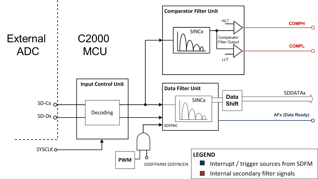
GUID-F08272D3-9EC0-4E9B-BABD-ED1E6DA9BFAF-low.pngFigure 2-8 SDFM Module With Both Primary and Secondary Filter Blocks on the TMS320F2837xD MCU