TIDA029A july   2019  – june 2023 CC2640R2F-Q1 , CC2642R , CC2642R-Q1


  1.   1
  2.   Bluetooth Angle of Arrival (AoA) Antenna Design
  3.   Trademarks
  4. 1Introduction
  5. 2Angle of Arrival Antenna Design Considerations
    1. 2.1 Antenna Spacing
    2. 2.2 RF Switch Considerations
  6. 3Dipole Antenna Array
    1. 3.1 Dipole Antenna Strengths and Weaknesses
    2. 3.2 Angle Measurement Plane
    3. 3.3 PCB Implementation
    4. 3.4 Two Dipole Array Test Results
      1. 3.4.1 Total Radiated Power (TRP)
      2. 3.4.2 Measuring Antenna 1 and 2 Phase Difference
        1. 3.4.2.1 Bare PCB
        2. 3.4.2.2 PCB + RF Absorbing Material
        3. 3.4.2.3 PCB + RF Absorbing Material + Tin-Plated Copper Foil
        4. 3.4.2.4 PCB + RF Absorbing Material + Tin-Plated Copper Foil + Metal
      3. 3.4.3 Phase Difference vs Distance
  7. 4Calculating AoA From IQ Measurements
    1. 4.1 Dipole Antenna Array Uncompensated Angle of Arrival Results
      1. 4.1.1 Bare PCB Uncompensated AoA
      2. 4.1.2 PCB + RF Absorbing Material Uncompensated AoA
      3. 4.1.3 PCB + RF Absorbing Material + Tin-Plated Copper Foil Uncompensated AoA
      4. 4.1.4 PCB + RF Absorbing Material + Tin-Plated Copper Foil + Metal Uncompensated AoA
    2. 4.2 Dipole Antenna Array Compensated AoA Results
      1. 4.2.1 Bare PCB AoA With Compensation
      2. 4.2.2 PCB + RF Absorbing Material + Tin-Plated Copper Foil Compensated AoA
      3. 4.2.3 PCB + RF Absorbing Material + Tin-Plated Copper Foil + Metal Compensated AoA
      4. 4.2.4 Hardware Setup Compensated Results Comparison
  8. 5References
  9. 6Revision History

Two Dipole Array Test Results

The following sections show various test results based off the TIDA-01632 antenna design. All test results were taken in an anechoic chamber using the turntable shown in Figure 3-13, capable of rotating the base and the arm by 1° increments.
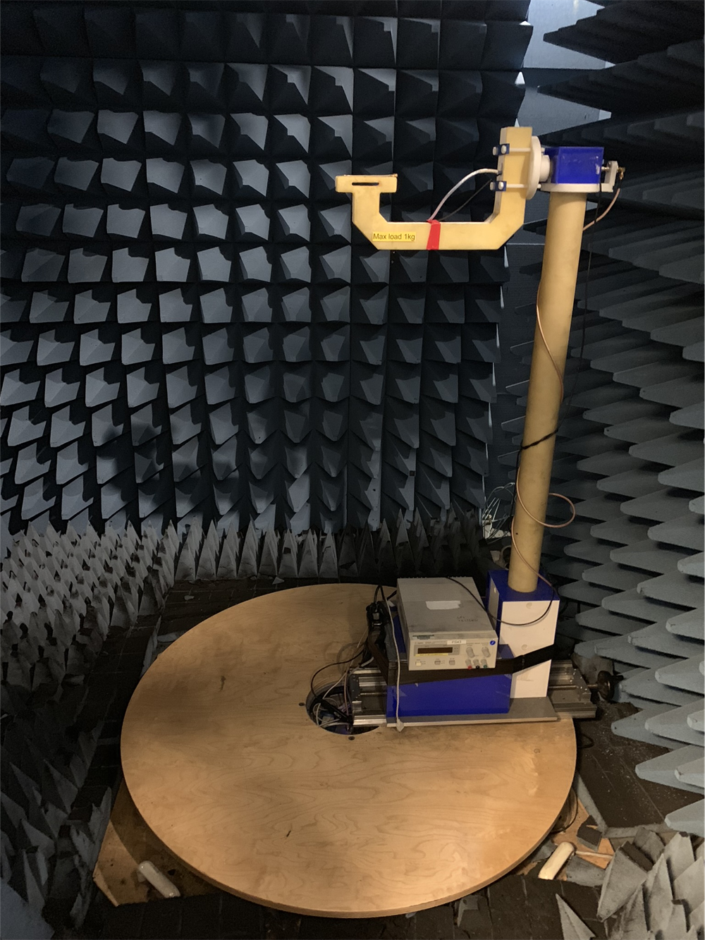
GUID-16879663-9D35-4D6A-ABA9-49FA4F9CDC2C-low.pngFigure 3-13 Turntable Test Setup

Figure 3-14 shows the TIDA-01632 PCB mounted on the arm of the turntable and Figure 3-15 shows the rest of the anechoic chamber.
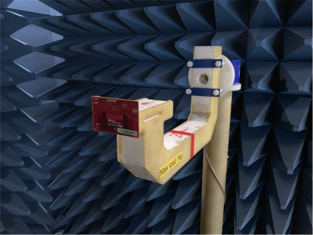
GUID-FBDAEF9E-1277-4B45-B1D9-DE20092AA5DC-low.pngFigure 3-14 PCB Mounted on Turntable Arm
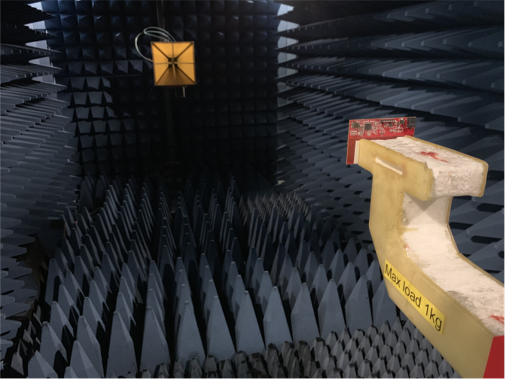
GUID-8CB5EABD-1C95-46AA-9F79-5B4D109E024B-low.pngFigure 3-15 Anechoic Chamber