TIDA029A july 2019 – june 2023 CC2640R2F-Q1 , CC2642R , CC2642R-Q1
- 1
- Bluetooth Angle of Arrival (AoA) Antenna Design
- Trademarks
- 1Introduction
- 2Angle of Arrival Antenna Design Considerations
- 3Dipole Antenna Array
- 4Calculating AoA From IQ Measurements
- 5References
- 6Revision History
3.1 Dipole Antenna Strengths and Weaknesses
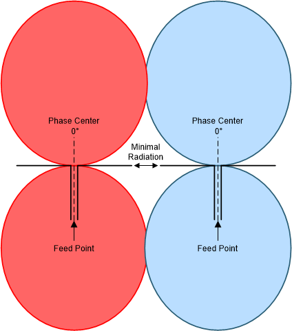
The dipole antenna has two big strengths and one weakness in an AoA application. The first strength is that dipole antennas have a constant phase center that is always at the feeding point (in the middle of the antenna). This is important as the antenna does not add any phase errors due to a shifting phase center. Second, the dipole antenna does not receive or transmit RF power in the direction of its own axis. Antenna coupling is therefore minimized even with the antennas being close to one another (phase centers <½ λ). Figure 3-1 shows the dipole antenna radiation pattern and phase center.
 Figure 3-1 Dipole Antenna Radiation Pattern and Phase Center
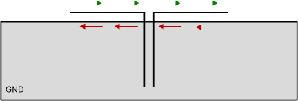
The main weakness of the dipole antenna is that it is differential and requires isolation from ground. This requirement directly conflicts with the ground plane of the Bluetooth Low Energy receiver. If the ground plane is too close to the antenna, the antenna is effectively shorted because the ground plane reflects the inverse of the incoming wave. However, if the ground plane is further away, it will still reflect RF power back to the antenna and reduce its efficiency.
 Figure 3-2 Boundary Current With GND Plane
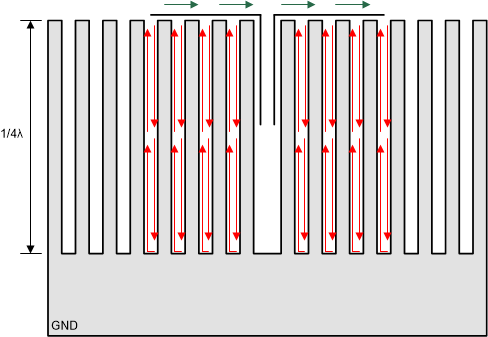
To resolve the ground plane issue, a corrugated ground plane is implemented. The corrugated ground plane removes the boundary current by shifting the reflected phase 180° per finger by taking the boundary current on a ½ λ detour. Therefore, each segment cancels the effect of the neighboring segments and the net effect is zero current and an in-phase reflection as Figure 3-3 shows.
 Figure 3-3 Boundary Current With Corrugated GND Plane