TIDA029A july 2019 – june 2023 CC2640R2F-Q1 , CC2642R , CC2642R-Q1
- 1
- Bluetooth Angle of Arrival (AoA) Antenna Design
- Trademarks
- 1Introduction
- 2Angle of Arrival Antenna Design Considerations
- 3Dipole Antenna Array
- 4Calculating AoA From IQ Measurements
- 5References
- 6Revision History
4 Calculating AoA From IQ Measurements
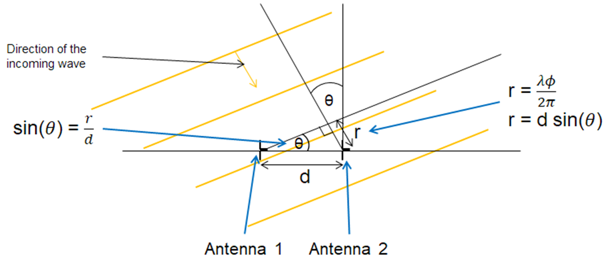
In Section 3, the measured phases were used to calculate a phase difference between the two antennas with different hardware setups. The next step is to calculate AoA based on the measured phase difference. With a known spacing between the antennas (d), and phase difference between the two antennas measured (Φ), the AoA can be calculated using simple trigonometry as Figure 4-1 shows.
 Figure 4-1 AoA Equations
The equations in Figure 4-1 can be simplified to Equation 4.

Note that r is the distance to antenna 2 that the incident wave needs to travel after arriving at antenna 1. Because the phase difference is known (Φ), the extra distance r is equal to the wavelength of the incoming signal times Φ / (2π). For more information on the AoA calculation, see the SimpleLink Academy -> RTLS Toolbox -> Angle of Arrival (AoA). Performing the arcsin() function using the wavelength, known antenna phase center spacing, and calculated phase difference between the two antennas, the AoA is calculated.
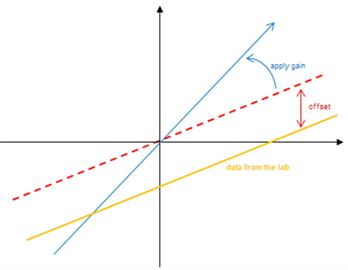
After the AoA is calculated, the value may need to be compensated due to variation in results across frequency and antenna design. Therefore, a constant gain, an offset, or both may be used to improve the AoA results.
 Figure 4-2 Compensation to Linear
Plot
Figure 4-2 Compensation to Linear
PlotFor more information on AoA compensation, see the Angle Compensation section of the SimpleLink™ CC2640R2 SDK BLE-Stack User’s Guide.