TIDA029A july 2019 – june 2023 CC2640R2F-Q1 , CC2642R , CC2642R-Q1
- 1
- Bluetooth Angle of Arrival (AoA) Antenna Design
- Trademarks
- 1Introduction
- 2Angle of Arrival Antenna Design Considerations
- 3Dipole Antenna Array
- 4Calculating AoA From IQ Measurements
- 5References
- 6Revision History
3.2 Angle Measurement Plane
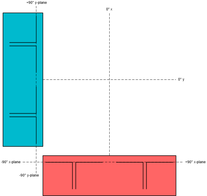
A single dipole antenna array can measure the AoA of an incoming signal in one plane (that is, x, y, or z). If it is required to measure the direction of a signal in another plane, an additional dipole antenna array is required aligned parallel to the plane.
 Figure 3-4 Antenna Array
Orientation
Figure 3-4 Antenna Array
OrientationThis can be done on a single PCB such as the SimpleLink™ Angle of Arrival BoosterPack or by using another single antenna array PCB such as the TIDA-01632 reference design in another orientation.
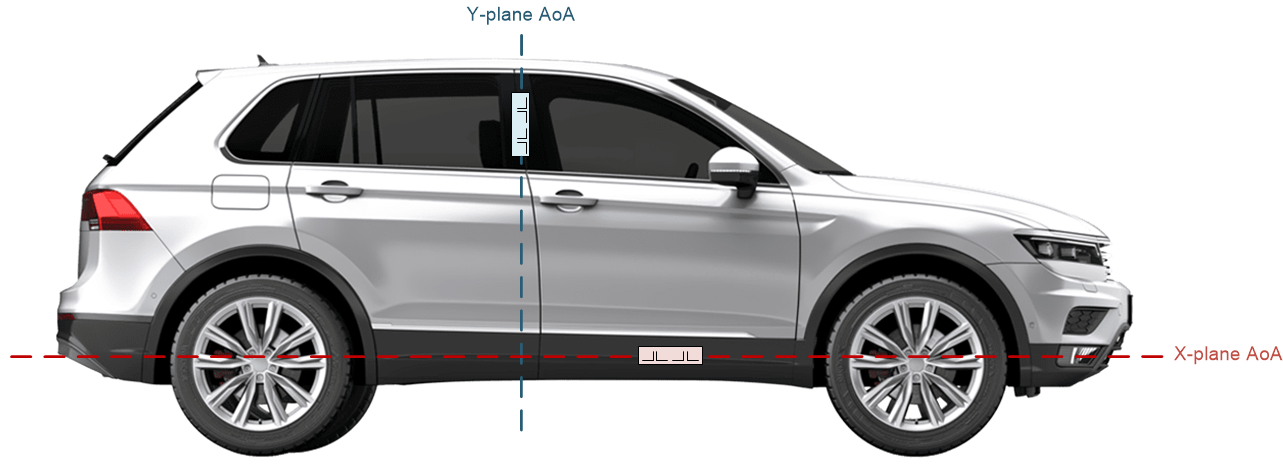
 Figure 3-5 Measuring AoA in Two Planes With Multiple Dipole Antenna Arrays
In this example, the blue antenna array measures AoA in the y-plane, determining how high or low the key is located relative to the antenna array regardless of the key being located to the left, right, or center of the vehicle. The red antenna array measures AoA in the x-plane, determining if the key is to the left, right, or center of the vehicle passenger door regardless of how high or low the key is relative to the vehicle.