SLAA148A October   2002  – October 2018


  1.   Interfacing the 3-V MSP430™ MCUs to 5-V Circuits
    1.     Trademarks
    2. 1 Introduction
    3. 2 Definitions
      1. 2.1 Specification Values of MSP430 MCU
      2. 2.2 External System Definitions
    4. 3 Input Interfaces
      1. 3.1 Resistor-Divider Input Interfaces
      2. 3.2 Transistor Input Interface
      3. 3.3 Op-Amp Input Interface
      4. 3.4 TPL7407LA Input Interface
      5. 3.5 Integrated-Circuit Input Interface
      6. 3.6 Analog Input Interface
    5. 4 Output Interfaces
      1. 4.1 Transistor Output Interface
      2. 4.2 Interface to CMOS-TTL Inputs
      3. 4.3 Interface to TPL7407LA Inputs
      4. 4.4 Op-Amp Output Interface
      5. 4.5 Integrated-Circuit Output Interface
    6. 5 Bidirectional Interfaces
      1. 5.1 Simple Bidirectional Op-Amp Interface
      2. 5.2 Integrated-Circuit I/O Interface
    7. 6 Power Supplies
    8. 7 Summary
    9. 8 References
  2.   Revision History

Analog Input Interface

The same resistor divider solution described for the digital interfaces in Section 3.1 can be used for the analog ADC12 inputs. Figure 5 shows the connection of a 5-V Hall-sensor current interface to the ADC12 input Ax. Section 3.1 describes the worst case equations for the resistor divider.
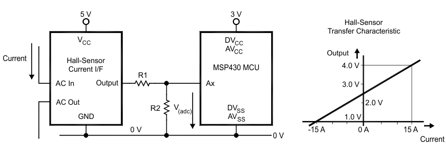
analog-adc12-input-interface-from-5-v-to-3-v.gifFigure 5. Analog ADC12 Input Interface From 5 V to 3 V

If the external peripheral cannot deliver the current for the resistor divider, a unity-gain op amp can be placed between the peripheral output and resistor R1.

The ADC12 sample time t(sample) must be adapted to the impedance R1||R2 of the resistor divider. For more information, see the ADC12 chapter of the MSP430x4xx Family User’s Guide or the MSP430x1xx Family User’s Guide.