SLVA372D November 2009 – November 2022 LM2577 , LM2585 , LM2586 , LM2587 , LM2588 , LMR61428 , LMR62014 , LMR62421 , LMR64010 , TL1451A , TL5001 , TL5001A , TLV61220 , TPS40210 , TPS40211 , TPS43000 , TPS61000 , TPS61002 , TPS61005 , TPS61006 , TPS61007 , TPS61010 , TPS61012 , TPS61013 , TPS61014 , TPS61015 , TPS61016 , TPS61020 , TPS61021A , TPS61024 , TPS61025 , TPS61026 , TPS61027 , TPS61028 , TPS61029 , TPS61029-Q1 , TPS61030 , TPS61031 , TPS61032 , TPS61046 , TPS61070 , TPS61071 , TPS61072 , TPS61073 , TPS61085 , TPS61086 , TPS61087 , TPS61088 , TPS61089 , TPS61090 , TPS61091 , TPS61092 , TPS61093 , TPS61093-Q1 , TPS61097-33 , TPS61100 , TPS61107 , TPS61120 , TPS61121 , TPS61122 , TPS61130 , TPS61131 , TPS61170 , TPS61175 , TPS61175-Q1 , TPS61200 , TPS61201 , TPS61202 , TPS61220 , TPS61221 , TPS61222 , TPS61230A , TPS61235P , TPS61236P , TPS61240 , TPS61241 , TPS61253 , TPS61254 , TPS61256 , TPS61258 , TPS61259 , TPS612592 , TPS61291 , TPS65070 , TPS65072 , TPS65073 , TPS65100 , TPS65100-Q1 , TPS65101 , TPS65105 , TPS65130 , TPS65131 , TPS65131-Q1 , TPS65132 , TPS65132S , TPS65133 , TPS65137 , TPS65140 , TPS65140-Q1 , TPS65141 , TPS65142 , TPS65145 , TPS65145-Q1 , TPS65150 , TPS65150-Q1 , TPS65154 , TPS65155 , TPS65160 , TPS65160A , TPS65161 , TPS65161A , TPS65161B , TPS65162 , TPS65163 , TPS65167A , TPS65170 , TPS65175 , TPS65175B , TPS65175C , TPS65176 , TPS65177 , TPS65177A , TPS65178 , TPS65631 , TPS65631W , TPS65632 , TPS65632A , TPS65640 , TPS65642 , TPS65642A , UCC39411
- Basic Calculation of a Boost Converter's Power Stage
- 1 Basic Configuration of a Boost Converter
- 2 Calculate the Maximum Switch Current
- 3 Inductor Selection
- 4 Rectifier Diode Selection
- 5 Output Voltage Setting
- 6 Input Capacitor Selection
- 7 Output Capacitor Selection
- 8 Equations to Calculate the Power Stage of a Boost Converter
- 9 References
- 10Revision History
3 Inductor Selection
Often data sheets give a range of recommended inductor values. If this is the case, it is recommended to choose an inductor from this range. The higher the inductor value, the higher is the maximum output current because of the reduced ripple current.
The lower the inductor value, the smaller is the solution size. Note that the inductor must always have a higher current rating than the maximum current given in Equation 4 because the current increases with decreasing inductance.
For parts where no inductor range is given, the following equation is a good estimation for the right inductor:
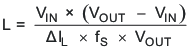
VIN = typical input
voltage
VOUT = desired output
voltage
fS = minimum switching
frequency of the converter
ΔIL = estimated
inductor ripple current, see below
The inductor ripple current cannot be calculated with Equation 1 because the inductor is not known. A good estimation for the inductor ripple current is 20% to 40% of the output current.
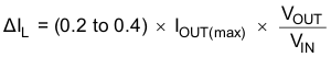
ΔIL
= estimated inductor ripple current
IOUT(max) = maximum output current necessary in the
application