SPRACM3E August 2021 – January 2023 F29H850TU , F29H859TU-Q1 , TMS320F280021 , TMS320F280021-Q1 , TMS320F280023 , TMS320F280023-Q1 , TMS320F280023C , TMS320F280025 , TMS320F280025-Q1 , TMS320F280025C , TMS320F280025C-Q1 , TMS320F280033 , TMS320F280034 , TMS320F280034-Q1 , TMS320F280036-Q1 , TMS320F280036C-Q1 , TMS320F280037 , TMS320F280037-Q1 , TMS320F280037C , TMS320F280037C-Q1 , TMS320F280038-Q1 , TMS320F280038C-Q1 , TMS320F280039 , TMS320F280039-Q1 , TMS320F280039C , TMS320F280039C-Q1 , TMS320F280040-Q1 , TMS320F280040C-Q1 , TMS320F280041 , TMS320F280041-Q1 , TMS320F280041C , TMS320F280041C-Q1 , TMS320F280045 , TMS320F280048-Q1 , TMS320F280048C-Q1 , TMS320F280049 , TMS320F280049-Q1 , TMS320F280049C , TMS320F280049C-Q1 , TMS320F28384D , TMS320F28384S , TMS320F28386D , TMS320F28386S , TMS320F28388D , TMS320F28388S , TMS320F28P650DH , TMS320F28P650DK , TMS320F28P650SH , TMS320F28P650SK , TMS320F28P659DH-Q1 , TMS320F28P659DK-Q1 , TMS320F28P659SH-Q1
- Using the Fast Serial Interface (FSI) With Multiple Devices in an Application
- Trademarks
- 1Introduction to the FSI Module
- 2FSI Applications
- 3Handshake Mechanism
- 4Sending and Receiving FSI Data Frames
- 5Daisy-Chain Topology Tests
- 6Star Topology Tests
-
7Event Synchronization Over FSI
- 7.1 Introduction
- 7.2 C2000Ware FSI EPWM Sync Examples
- 7.3 Additional Tips and Usage of FSI Event Sync
- 8References
- 9Revision History
5 Daisy-Chain Topology Tests
In order to demonstrate the communication speed and different configurations for FSI, daisy-chain connections for two device and three device configurations have been tested and validated. The test hardware utilized is composed of multiple F280025C ControlCARD Evaluation Modules and TMDSFSIADAPEVMs.
2. The hardware pass-through feature is tested with LAUNCHXL-F280039C and TMDSFSIADAPEVMs as this feature is only available in this device.
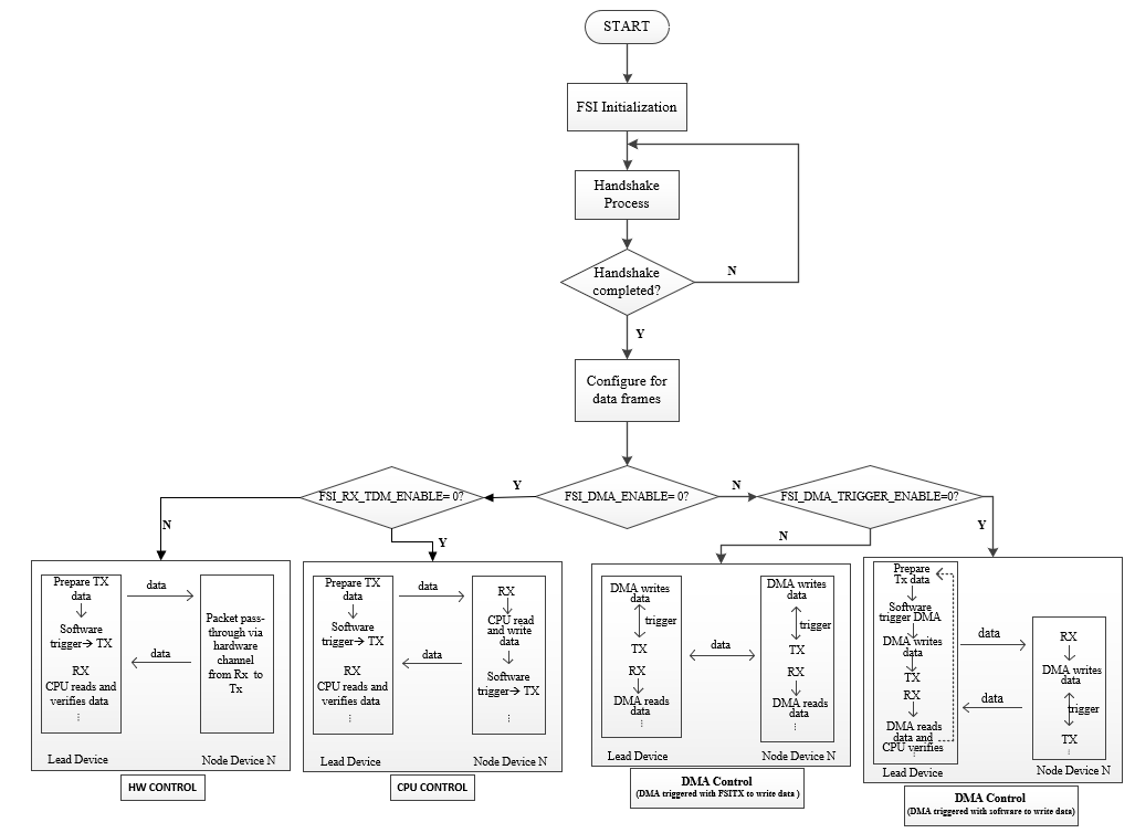
The tested example projects can be found within the C2000WARE download. All test results were collected using optimization level 2, configured within Code Composer Studio™ (CCS). Changing the optimization level may yield different results. An overall description of the tested projects is shown in Table 5-1. For better understanding, a general software flow chart with different project settings is shown in Figure 5-1.
| Project | Description | Settings |
|---|---|---|
| fsi_ex_daisy_handshake_lead | Project for the lead device in the daisy-chain loop. | ① [#define
FSI_DMA_ENABLE 0 && #define FSI_RX_TDM_ENABLE 0] represents
FSI communication using CPU control. ② [#define FSI_DMA_ENABLE 1 && #define TX_DMA_TRIGGER_ENABLE 0 && #define FSI_RX_TDM_ENABLE 0] represents FSI communication using DMA control, and using software to trigger DMA for the transmitted data (manually). ③ [#define FSI_DMA_ENABLE 1 && #define TX_DMA_TRIGGER_ENABLE 1 && #define FSI_RX_TDM_ENABLE 0] represents FSI communication using DMA control, and enabling FSITX to trigger DMA for the transmitted data. ④ [#define FSI_DMA_ENABLE 0 && #define FSI_RX_TDM_ENABLE 1] represents FSI communication using HW RX TDM control |
| fsi_ex_daisy_handshake_node | Project for the N-1 other devices (N>=2) in the daisy-chain loop. |
 Figure 5-1 Software Flow Chart With
Different Project Settings