SPRACM3E August 2021 – January 2023 F29H850TU , F29H859TU-Q1 , TMS320F280021 , TMS320F280021-Q1 , TMS320F280023 , TMS320F280023-Q1 , TMS320F280023C , TMS320F280025 , TMS320F280025-Q1 , TMS320F280025C , TMS320F280025C-Q1 , TMS320F280033 , TMS320F280034 , TMS320F280034-Q1 , TMS320F280036-Q1 , TMS320F280036C-Q1 , TMS320F280037 , TMS320F280037-Q1 , TMS320F280037C , TMS320F280037C-Q1 , TMS320F280038-Q1 , TMS320F280038C-Q1 , TMS320F280039 , TMS320F280039-Q1 , TMS320F280039C , TMS320F280039C-Q1 , TMS320F280040-Q1 , TMS320F280040C-Q1 , TMS320F280041 , TMS320F280041-Q1 , TMS320F280041C , TMS320F280041C-Q1 , TMS320F280045 , TMS320F280048-Q1 , TMS320F280048C-Q1 , TMS320F280049 , TMS320F280049-Q1 , TMS320F280049C , TMS320F280049C-Q1 , TMS320F28384D , TMS320F28384S , TMS320F28386D , TMS320F28386S , TMS320F28388D , TMS320F28388S , TMS320F28P650DH , TMS320F28P650DK , TMS320F28P650SH , TMS320F28P650SK , TMS320F28P659DH-Q1 , TMS320F28P659DK-Q1 , TMS320F28P659SH-Q1
- Using the Fast Serial Interface (FSI) With Multiple Devices in an Application
- Trademarks
- 1Introduction to the FSI Module
- 2FSI Applications
- 3Handshake Mechanism
- 4Sending and Receiving FSI Data Frames
- 5Daisy-Chain Topology Tests
- 6Star Topology Tests
-
7Event Synchronization Over FSI
- 7.1 Introduction
- 7.2 C2000Ware FSI EPWM Sync Examples
- 7.3 Additional Tips and Usage of FSI Event Sync
- 8References
- 9Revision History
7.1.1 Requirement of Event Sync for Distributed Systems
In any real-time control system where more than one device operates together to perform a task, the devices send and receive critical information based on the control loop functions. The time to transmit the data from one device to the other can be different from device to device because of multiple factors including the distance between the devices, slight deviation in device clock during operation due to manufacturing uncertainties, thermal effects, aging, and so forth. The time-critical control loop may fail if the data received at the any of the device in the network is delayed or incorrect. It becomes important for the user to synchronize the operation of devices at regular intervals of time to correct the asynchronization due to uncertainties. The synchronization can be necessary for any of the events such as PWM signals, ADC Start of Conversions (ADC SoC), external triggers through GPIOs, and so forth.
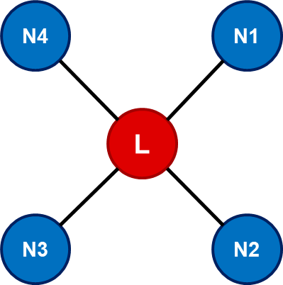
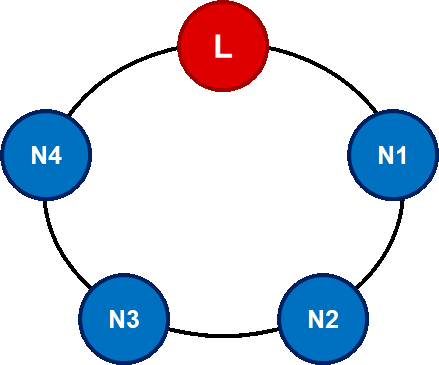
In a real-time application, multiple configurations with lead and node devices can be arranged such as star network or daisy-chain network as described in Section 2. The star and daisy-chain configuration can be briefly understood from Figure 7-1 and Figure 7-2. All the node devices can be operating at different voltage levels and can be at different distances from the controller. Because of this, there may be significant difference in the time of any control signal sent from the lead device and the signal being received at each node device. The signal at each node device will arrive at different instances in time resulting in asynchronous operation of all the operating devices at every node. If the signals are fed to respective devices at different intervals of time, it can generate spurious operation which can cause the control loop application to breakdown. It becomes very important that the devices operate in synchronism to avoid the failure of system.
The aim is to synchronize all devices in the network topology with minimum amount of trigger latency and event jitter and also without using any additional wires other than the existing communication channel between the devices. This event synchronization has been achieved using the Fast Serial Interface (FSI) communication protocol.
 Figure 7-1 Star Network
Configuration
 Figure 7-2 Daisy-Chain Network
Configuration