SPRUIF3B May 2017 – March 2019
-
DRA79x EVM CPU board
- Trademarks
- 1 Introduction
- 2 Overview
- 3
Hardware
- 3.1 Hardware Architecture
- 3.2 DRA71x, DRA79x, TDA2E-17, and AM570x Processor
- 3.3 Power Architecture
- 3.4 Reset Structure
- 3.5 Clocks
- 3.6
Memory
- 3.6.1 SDRAM Memory
- 3.6.2 QSPI Flash Memory
- 3.6.3 EMMC Flash Memory
- 3.6.4 MicroSD Card Cage
- 3.6.5 GPMC NOR Flash Memory
- 3.6.6 GPMC NAND Flash Memory
- 3.6.7 Boot Modes
- 3.6.8 JTAG/Emulator and Trace
- 3.6.9 UART Terminal
- 3.6.10 DCAN and CAN Interfaces
- 3.6.11 Universal Serial Bus (USB)
- 3.6.12 Wired Ethernet
- 3.6.13 Video Output
- 3.6.14 Video Input
- 3.6.15 Mini-PCIe
- 3.6.16 Media Local Bus (MLB)
- 3.6.17 Audio
- 3.6.18 COM8 Module Interface
- 3.6.19 eFuse Programming Supply
- 3.6.20 User Interface LEDs
- 3.6.21 Power Monitoring
- 3.6.22 I2C Peripheral Map
- 3.6.23 GPIO List
- 3.6.24 I/O Expander List
- 3.6.25 Configuration EEPROM
- 4
Signal Multiplex Logic
- 4.1 GPMC and QSPI Selection (MUX A)
- 4.2 GPMC, VIN1, and VOUT3 Selection (MUX B)
- 4.3 GPMC and EMMC Selection (MUX C)
- 4.4 VIN2A and EMU Selection (MUX D, MUX E)
- 4.5 VIN2A and RGMII1 Selection (MUX F)
- 4.6 RGMII0 and VIN1B Selection (MUX J)
- 4.7 SPI2 and UART3 Selection (MUX K)
- 4.8 DCAN2 and I2C3 Selection (MUX L)
- 5 USB3 Supported Configurations
- 6 References
- Revision History
2 Overview
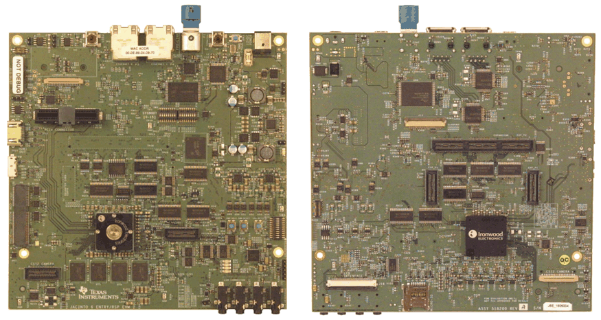
An EVM system is comprised of a CPU board with one or more application boards. The CPU board (see Figure 1) can be used as a stand-alone for software debug and development. Each EVM system is designed to let customers evaluate the processor performance and flexibility in the following targeted markets:
- Automotive, radio sound processor (RSP), display audio, gateway, and infotainment applications
- Automotive, ADAS applications
The CPU board contains the DRA71x, DRA79x, TDA2Ex-17, and AM570x (superset part) applications processor, a companion power solution (LP8733 and LP8732), DDR3 DRAM, several types of flash memories (QSPI, eMMC, NAND, and NOR), and interface ports and expansion connectors. The board provides additional support components that provide software debugging, signal routing, and configuration controls that are not needed in a final product. Different versions of the CPU boards will be built to support the development process that includes the following:
- Socketed processor for wakeup, early software development, and quick and easy chip revision evaluation
- Soldered-down processor for high-performance use cases and evaluations
All other onboard components are soldered-down.
 Figure 1. DRA71x, DRA79x, TDA2Ex-17, and AM570x CPU Board (Front and Back Views)