SLVAEX9B April 2022 – August 2022 ESD122 , ESD1LIN24-Q1 , ESD204 , ESD224 , ESD2CAN24-Q1 , ESD2CANFD24 , ESD2CANXL24-Q1 , ESD321 , ESD341 , ESD351 , ESD401 , ESD451 , ESD751 , ESD751-Q1 , ESD752 , ESD761 , ESD761-Q1 , ESD762 , ESDS302 , ESDS304 , ESDS312 , ESDS314 , SN65220 , SN65240 , TPD1E01B04 , TPD1E01B04-Q1 , TPD1E04U04 , TPD1E05U06 , TPD1E05U06-Q1 , TPD1E0B04 , TPD1E10B06 , TPD1E10B09-Q1 , TPD1E1B04 , TPD1E6B06 , TPD2E001 , TPD2E001-Q1 , TPD2E007 , TPD2E009 , TPD2E1B06 , TPD2E2U06 , TPD2EUSB30 , TPD2EUSB30A , TPD2S017 , TPD3E001 , TPD3F303 , TPD4E001 , TPD4E001-Q1 , TPD4E002 , TPD4E004 , TPD4E02B04 , TPD4E02B04-Q1 , TPD4E05U06-Q1 , TPD4E101 , TPD4E110 , TPD4E1B06 , TPD4E1U06 , TPD4E6B06 , TPD4F003 , TPD4S009 , TPD4S012 , TPD5E003 , TPD6E001 , TPD6E004 , TPD6E05U06 , TPD8S009 , TSD05 , TSD05C , TSM24A-Q1 , TSM24CA-Q1 , TSM36A , TVS0500 , TVS0701 , TVS1400 , TVS1401 , TVS2200 , TVS2701 , TVS3301 , UC1611-SP , UC2610 , UC3610 , UC3611 , UC3611M
- Abstract
- Trademarks
- 1Definitions of ESD Device Specifications
- 2ESD Layout Tips
-
3ESD Solutions by Package Types
- 3.1 0201 2-pin SON (TI: DPL) | 0.6 mm x 0.3 mm
- 3.2 0402 2-pin SON (TI: DPY) | 1.0 mm × 0.6 mm
- 3.3 2-pin SOD-523 (TI: DYA) | 1.2 mm x 0.8 mm
- 3.4 3-pin SOT-9X3 (TI: DRT) | 1 mm × 1 mm
- 3.5 3-pin SC70 (TI: DCK) | 2 mm × 1.25 mm
- 3.6 3-pin SOT23 (TI:DBZ) | 3.04 mm × 2.64 mm
- 3.7 4-pin SON (TI: DPW) | 0.8 mm × 0.8 mm
- 3.8 5-pin SOT-5X3 (TI: DRL) | 1.6 mm × 1.2 mm
- 3.9 5-pin SOT-23 (TI: DBV) | 2.9 mm × 1.6 mm
- 3.10 6-pin SON (TI: DRY) | 1.45 mm × 1 mm
- 3.11 6-pin SOT-5X3 (TI: DRL) | 1.6 mm × 1.2 mm
- 3.12 6-pin SOT-23 (TI: DBV) | 1.6 mm × 2.9 mm
- 3.13 6-pin SC70 (TI: DCK) | 2.15 mm × 1.4 mm
- 3.14 8-pin SON (TI: DQD) | 1.35 mm × 1.7 mm
- 3.15 10-pin SON (TI: DQA) | 1 mm × 2.5 mm
- 4References
- 5Revision History
2.2 Limiting EMI From ESD
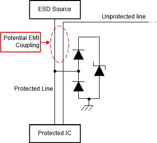
Without proper steps for suppression, fast transients such as ESD with high di/dt can cause electromagnetic interference (EMI). Figure 2-2 shows that the primary source of radiation occurs between the ESD source and the TVS.
 Figure 2-2 EMI Coupling Onto an Adjacent
Unprotected Trace
Figure 2-2 EMI Coupling Onto an Adjacent
Unprotected TraceEven without inductance L1 from Figure 2-1, the rapidly changing electric field during ESD can affect nearby circuits. Having any L1 would further amplify the EMI. The PCB designer should avoid any design practices in this region with unprotected PCB traces. In an ESD event, the potential EMI coupling with an unprotected line could damage the system by having direct contact with an IC or carrying the EMI further into the system. Use these 4 tips to limit EMI:
- Do not route unprotected circuits in the area between the ESD source and the TVS
- Place the TVS as close to the ESD source or connector as design rules allow
- Route with straight traces between the ESD source and the TVS, if possible
- If corners must be used, curves are preferred and a maximum of 45° is acceptable