SPRACY1 May 2021 F29H850TU , F29H859TU-Q1 , TMS320F2800132 , TMS320F2800133 , TMS320F2800135 , TMS320F2800137 , TMS320F2800152-Q1 , TMS320F2800153-Q1 , TMS320F2800154-Q1 , TMS320F2800155 , TMS320F2800155-Q1 , TMS320F2800156-Q1 , TMS320F2800157 , TMS320F2800157-Q1 , TMS320F280021 , TMS320F280021-Q1 , TMS320F280023 , TMS320F280023-Q1 , TMS320F280023C , TMS320F280025 , TMS320F280025-Q1 , TMS320F280025C , TMS320F280025C-Q1 , TMS320F280033 , TMS320F280034 , TMS320F280034-Q1 , TMS320F280036-Q1 , TMS320F280036C-Q1 , TMS320F280037 , TMS320F280037-Q1 , TMS320F280037C , TMS320F280037C-Q1 , TMS320F280038-Q1 , TMS320F280038C-Q1 , TMS320F280039 , TMS320F280039-Q1 , TMS320F280039C , TMS320F280039C-Q1 , TMS320F280040-Q1 , TMS320F280040C-Q1 , TMS320F280041 , TMS320F280041-Q1 , TMS320F280041C , TMS320F280041C-Q1 , TMS320F280045 , TMS320F280048-Q1 , TMS320F280048C-Q1 , TMS320F280049 , TMS320F280049-Q1 , TMS320F280049C , TMS320F280049C-Q1 , TMS320F28075 , TMS320F28075-Q1 , TMS320F28076 , TMS320F28374D , TMS320F28374S , TMS320F28375D , TMS320F28375S , TMS320F28375S-Q1 , TMS320F28376D , TMS320F28376S , TMS320F28377D , TMS320F28377D-EP , TMS320F28377D-Q1 , TMS320F28377S , TMS320F28377S-Q1 , TMS320F28378D , TMS320F28378S , TMS320F28379D , TMS320F28379D-Q1 , TMS320F28379S , TMS320F28384D , TMS320F28384D-Q1 , TMS320F28384S , TMS320F28384S-Q1 , TMS320F28386D , TMS320F28386D-Q1 , TMS320F28386S , TMS320F28386S-Q1 , TMS320F28388D , TMS320F28388S , TMS320F28P550SG , TMS320F28P550SJ , TMS320F28P559SG-Q1 , TMS320F28P559SJ-Q1 , TMS320F28P650DH , TMS320F28P650DK , TMS320F28P650SH , TMS320F28P650SK , TMS320F28P659DH-Q1 , TMS320F28P659DK-Q1 , TMS320F28P659SH-Q1
2 New Features for Multiple Phase Control
For a typical multiple phase power converter, there are two factors shown below, which require careful consideration.
- Proper phase control
Each ePWM module can be configured to allow a SyncIn pulse to cause the phase register (TBPHS) contents to be loaded into the time-base counter (TBCTR). Thus, by programming appropriate values into TBPHS, multiple PWM modules can address some power topologies that rely on phase relationship between legs (or stages) for correct operation, like interleaved PFC, interleaved LLC, and so forth. Basically, the phase relationship for N phases by setting the TBPHS values can be given with the following formula shown in Equation 1.
Equation 1. TBPHS(N,M) = (TBPRD/N) x (M-1)where, N = number of phases M = PWM module number.
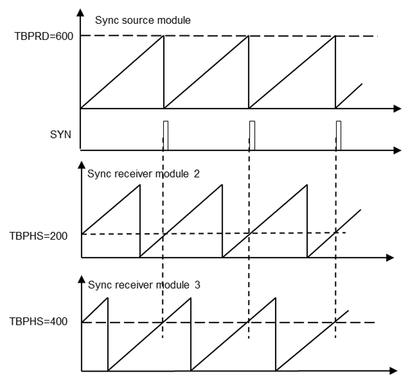
For example, for the 3-phase case (N=3), TBPRD = 600; TBPHS(3,2) = (600/3) x (2-1) = 200 (that is, Phase value for sync receiver module 2); TBPHS(3,3) = 400 (that is, Phase value for sync receiver module 3).
Figure 2-1 shows the associated timing waveforms for this phase relationship of 120°, and both sync receiver modules are synchronized to the sync source module.
 Figure 2-1 Timing Waveforms
Associated With Phase Control Between Three Modules
 - Update the registers across multiple
ePWM modules properly
In the actual applications, it is common that the EPWM outputs will change as required by the control loop, like variable duty cycles, frequencies, and so forth. It is critical to maintain the same phase relationship and synchronization among different ePWM modules after the change. Generally, in order to avoid corruption or spurious operation due to the register being asynchronously modified by software, shadow registers are enabled. The shadow register buffers or provides a temporary holding location for the active register. Users are responsible to select an event, when the shadow register's content will be transferred to the active register, which controls the hardware actions.