SPRACY1 May 2021 F29H850TU , F29H859TU-Q1 , TMS320F2800132 , TMS320F2800133 , TMS320F2800135 , TMS320F2800137 , TMS320F2800152-Q1 , TMS320F2800153-Q1 , TMS320F2800154-Q1 , TMS320F2800155 , TMS320F2800155-Q1 , TMS320F2800156-Q1 , TMS320F2800157 , TMS320F2800157-Q1 , TMS320F280021 , TMS320F280021-Q1 , TMS320F280023 , TMS320F280023-Q1 , TMS320F280023C , TMS320F280025 , TMS320F280025-Q1 , TMS320F280025C , TMS320F280025C-Q1 , TMS320F280033 , TMS320F280034 , TMS320F280034-Q1 , TMS320F280036-Q1 , TMS320F280036C-Q1 , TMS320F280037 , TMS320F280037-Q1 , TMS320F280037C , TMS320F280037C-Q1 , TMS320F280038-Q1 , TMS320F280038C-Q1 , TMS320F280039 , TMS320F280039-Q1 , TMS320F280039C , TMS320F280039C-Q1 , TMS320F280040-Q1 , TMS320F280040C-Q1 , TMS320F280041 , TMS320F280041-Q1 , TMS320F280041C , TMS320F280041C-Q1 , TMS320F280045 , TMS320F280048-Q1 , TMS320F280048C-Q1 , TMS320F280049 , TMS320F280049-Q1 , TMS320F280049C , TMS320F280049C-Q1 , TMS320F28075 , TMS320F28075-Q1 , TMS320F28076 , TMS320F28374D , TMS320F28374S , TMS320F28375D , TMS320F28375S , TMS320F28375S-Q1 , TMS320F28376D , TMS320F28376S , TMS320F28377D , TMS320F28377D-EP , TMS320F28377D-Q1 , TMS320F28377S , TMS320F28377S-Q1 , TMS320F28378D , TMS320F28378S , TMS320F28379D , TMS320F28379D-Q1 , TMS320F28379S , TMS320F28384D , TMS320F28384D-Q1 , TMS320F28384S , TMS320F28384S-Q1 , TMS320F28386D , TMS320F28386D-Q1 , TMS320F28386S , TMS320F28386S-Q1 , TMS320F28388D , TMS320F28388S , TMS320F28P550SG , TMS320F28P550SJ , TMS320F28P559SG-Q1 , TMS320F28P559SJ-Q1 , TMS320F28P650DH , TMS320F28P650DK , TMS320F28P650SH , TMS320F28P650SK , TMS320F28P659DH-Q1 , TMS320F28P659DK-Q1 , TMS320F28P659SH-Q1
2.3.2 Boundary Case
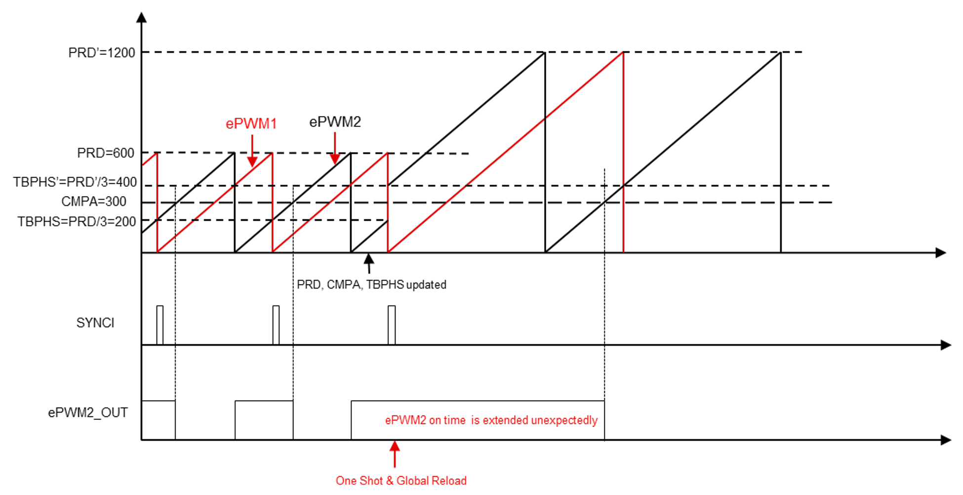
Considering all the possible operation conditions, the below corner case will be discussed, as shown in Figure 2-7. ePWM2 is configured to enable the phase shift to ePWM1 with 120°, where the TBPHS is PRD/3=200. And ePWM2 output sets high at CTR = Zero, and clears low at CTR = CMPA, where CMPA=300 at the beginning. All the registers of ePWM1 and ePWM2 are enabled with global load and one shot mode, with the global load event defined as CTR = Zero of ePWM1. Assuming a sudden frequency change event occurs during the ISR, before the global load event, where the new period value PRD’ changes to 2*PRD=1200, and TBPHS’= PRD’/3=400, while CMPA stays the same as previous. Then, as shown in the Figure 2-7, when the next global load event comes, the time-base counter of ePWM2 will jump from 200 to 400, which means CTR = CMPA event will be missed in the first PWM cycle after the frequency changes. This might cause severe risks for the system, with the ePWM2 output on time extending unexpectedly.
 Figure 2-7 Corner Case During Variable
Frequency Applications