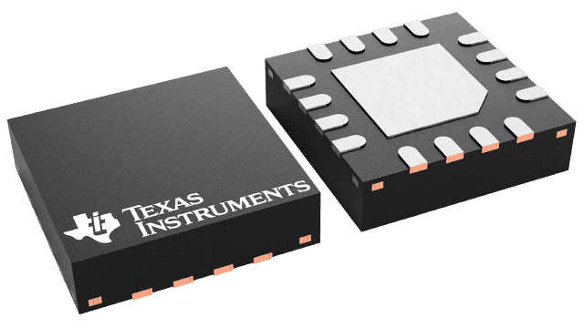
Packaging information
| Package | Pins WQFN (RTE) | 16 |
| Operating temperature range (°C) -55 to 125 |
| Package qty | Carrier 250 | SMALL T&R |
Features for the TPS57114-EP
- Two 12-mΩ (Typical) MOSFETs for High
Efficiency at 3.5-A Loads - 200-kHz to 2-MHz Switching Frequency
- 0.8-V ±1% Voltage Reference Over Temperature
(–55°C to 125°C) - Synchronizes to External Clock
- Adjustable Slow Start and Sequencing
- UV and OV Power-Good Output
- Thermally Enhanced 3-mm × 3-mm 16-Pin WQFN
- Supports Defense, Aerospace, and Medical Applications
- Controlled Baseline
- One Assembly and Test Site
- One Fabrication Site
- Available in Military (–55°C to 125°C)
Temperature Range - Extended Product Life Cycle
- Extended Product-Change Notification
- Product Traceability
Description for the TPS57114-EP
The TPS57114-EP device is a full-featured 6-V, 3.5-A, synchronous step-down current-mode converter with two integrated MOSFETs.
The TPS57114-EP enables small designs by integrating the MOSFETs, implementing current-mode control to reduce external component count, reducing inductor size by enabling up to 2-MHz switching frequency, and minimizing the IC footprint with a small 3-mm × 3-mm thermally-enhanced WQFN package.
The TPS57114-EP provides accurate regulation for a variety of loads with an accurate ±1% voltage reference (VREF) over temperature.
The integrated 12-mΩ MOSFETs and 515-µA typical supply current maximize efficiency. Entering shutdown mode by using the enable pin reduces the shutdown supply current to 5.5 µA.
The internal undervoltage lockout (UVLO) setting is 2.45 V, but programming the threshold with a resistor network on the enable pin can increase it. The slow-start pin controls the output-voltage start-up ramp. An open-drain power-good signal indicates the output is within 93% to 107% of its nominal voltage.
Frequency foldback and thermal shutdown protect the device during an overcurrent condition.
The SwitcherPro software tool, available at www.ti.com/switcherpro, supports the TPS57114-EP.
For more SWIFT documentation, see the TI website at www.ti.com/swift.
TPS57114-EP is a current mode controller used to support various topologies such as buck converter configuration.
Current mode control is a two-loop system. The switching power supply inductor is hidden within the inner current control loop. This simplifies the design of the outer voltage control loop and improves power supply performance in many ways, including better dynamics. The objective of this inner loop is to control the state-space averaged inductor current, but in practice, the instantaneous peak inductor current is the basis for control (switch current—equal to inductor current during the on time—is often sensed). If the inductor ripple current is small, peak inductor current control is nearly equivalent to average inductor current control.
The peak method of inductor current control functions by comparing the upslope of inductor current (or switch current) to a current program level set by the outer loop. The comparator turns the power switch off when the instantaneous current reaches the desired level. The current ramp is usually quite small compared to the programming level, especially when VIN is low. As a result, this method is extremely susceptible to noise. A noise spike is generated each time the switch turns on. A fraction of a volt coupled into the control circuit can cause it to turn off immediately, resulting in a subharmonic operating mode with much greater ripple. Circuit layout and bypassing are critically important to successful operation.
The peak current mode control method is inherently unstable at duty ratios exceeding 0.5, resulting in subharmonic oscillation. A compensating ramp (with slope equal to the inductor current downslope) is usually applied to the comparator input to eliminate this instability. Slope compensation must be added to the sensed current waveform or subtracted from the control voltage to ensure stability above a 50% duty cycle. A compensating ramp (with slope equal to the inductor current downslope) is usually applied to the comparator input to eliminate this instability. Current limit control design has numerous advantages: Current mode control provided peak switch current limiting – pulse-by-pulse current limit. The control loop is simplified as one pole because the output inductor is pushed to higher frequency, thus a two-pole system turns into two real poles. Thus, the system reduces to a first-order system and simplifies the control.Multiple converters can be paralleled and allow equal current sharing amount the various converters.Inherently provides for input voltage feed-forward because any perturbation in the input voltage is reflected in the switch or inductor current. Because switch or inductor current is a direct-control input, this perturbation is rapidly corrected.The error amplifier output (outer control loop) defines the level at which the primary current (inner loop) regulates the pulse duration and output voltage.
