SLLA284G July 2022 – September 2023 ISO5451 , ISO5452 , ISO5851 , ISO5852S , ISO7142CC , ISO7142CC-Q1 , ISO721 , ISO721-Q1 , ISO721M , ISO721M-EP , ISO722 , ISO7220A , ISO7220M , ISO7221A , ISO7221B , ISO7221C , ISO7221M , ISO722M , ISO7230C , ISO7230M , ISO7231C , ISO7231M , ISO7240C , ISO7240CF , ISO7240M , ISO7241C , ISO7241M , ISO7242C , ISO7242M , ISO7310-Q1 , ISO7310C , ISO7340-Q1 , ISO7340C , ISO7340FC , ISO7341-Q1 , ISO7341C , ISO7341FC , ISO7342-Q1 , ISO7342C , ISO7342FC , ISO7740 , ISO7741 , ISO7742 , ISO7760 , ISO7761 , ISO7762 , ISO7810 , ISO7820 , ISO7821 , ISO7830 , ISO7831 , ISO7840 , ISO7841 , ISO7842
1.1 Edge-Based Communication
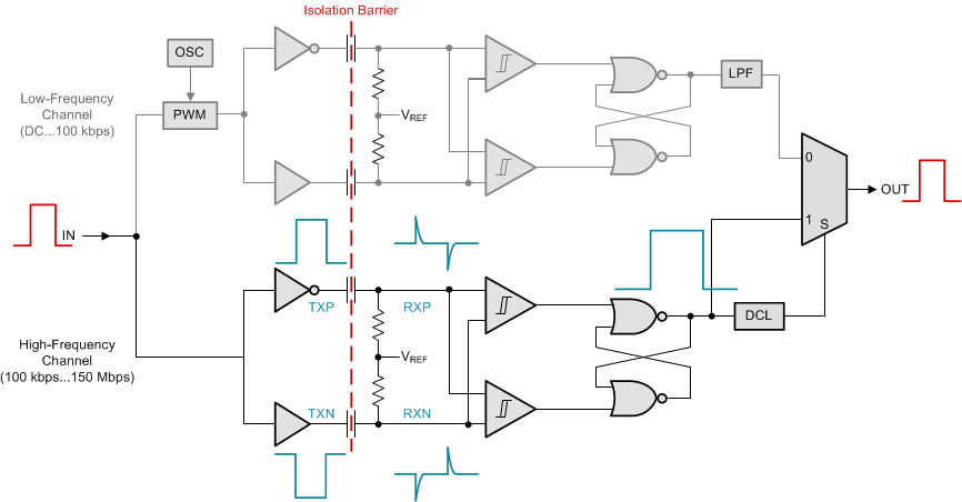
The conceptual block diagram of edge-based communication is shown in Figure 1-1. The isolators of ISO73xx, ISO74xx, ISO71xx, ISO76xx, ISO75xx, and ISO72xx families use this architecture in some form.
The device consists of at least two data channels, a high-frequency channel (HF) with a bandwidth from 100kbps up to 150Mbps, and a low-frequency channel (LF) covering the range from 100kbps down to dc.
In principle, a single-ended input signal entering the HF-channel is split into a differential signal via the inverter gate at the input. The following capacitor-resistor networks differentiate the signal into small and narrow transients, which then are converted into rail-to-rail differential pulses by two comparators. The comparator outputs drive a NOR-gate flip-flop whose output feeds an output multiplexer. A decision logic (DCL) at the driving output of the flip-flop measures the durations between signal transients. If the duration between two consecutive transients exceeds a certain time limit (as in the case of a low-frequency signal) the DCL forces the output-multiplexer to switch from the high-frequency to the low-frequency channel.
Because low-frequency input signals require the internal capacitors to assume prohibitively large values, these signals are pulse-width modulated (PWM) with the carrier frequency of an internal oscillator, thus creating a sufficiently high frequency, capable of passing the capacitive barrier. As the input is modulated, a low-pass filter (LPF) is needed to remove the high-frequency carrier from the actual data before passing it on to the output multiplexer.
 Figure 1-1 Conceptual Block Diagram of Edge-Based Architecture