SLLA284G July 2022 – September 2023 ISO5451 , ISO5452 , ISO5851 , ISO5852S , ISO7142CC , ISO7142CC-Q1 , ISO721 , ISO721-Q1 , ISO721M , ISO721M-EP , ISO722 , ISO7220A , ISO7220M , ISO7221A , ISO7221B , ISO7221C , ISO7221M , ISO722M , ISO7230C , ISO7230M , ISO7231C , ISO7231M , ISO7240C , ISO7240CF , ISO7240M , ISO7241C , ISO7241M , ISO7242C , ISO7242M , ISO7310-Q1 , ISO7310C , ISO7340-Q1 , ISO7340C , ISO7340FC , ISO7341-Q1 , ISO7341C , ISO7341FC , ISO7342-Q1 , ISO7342C , ISO7342FC , ISO7740 , ISO7741 , ISO7742 , ISO7760 , ISO7761 , ISO7762 , ISO7810 , ISO7820 , ISO7821 , ISO7830 , ISO7831 , ISO7840 , ISO7841 , ISO7842
2 Typical Applications for Digital Isolators and Isolated Functions
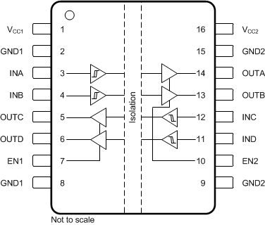
 Figure 2-1 Example Isolator in a 16-Pin Package
A pin diagram of a typical digital isolator is shown in Figure 2-1. It consists of two supplies: VCC1 and VCC2 , two grounds: GND1 and GND2, and input and output pins on either side referred to the respective grounds. That is, in Figure 2-1, pins 1 through 8 are referred to GND1 and pins 9 through 16 are referred to GND2.
Digital isolators use single-ended, CMOS or TTL logic, switching technology. The voltage range normally ranges 3 V to 5.5 V for both supplies, VCC1 and VCC2, though some devices may support a larger supply voltage range. For example, ISO78xx devices can work with supplies down to 2.25 V. When designing with digital isolators, it is important to keep in mind that due to the single-ended design structure, digital isolators do not conform to any specific interface standard and are only intended for isolating single-ended digital signal lines.
Isolated functions are devices where additional functionality, such as a transceiver or a gate-driver is integrated along with an isolator. An example is the integrated isolated-RS485 described later on in this section. Unlike digital isolators, an isolated function may need to conform to certain standards. For example, an isolated-I2C buffer will be compatible to the I2C standard. Also, an isolated function may run off higher supplies, for example, an isolated gate-driver may use ±15 V to be able to drive an IGBT gate.
Isolation is required in modern electrical systems for a variety of reasons. Some examples are to protect human operators from high voltage transients and preventing damage to expensive processors, ASICs or FPGAs in high-voltage systems, breaking the ground loop in communication networks and communication to high-side devices in motor drive or power converter systems. Examples of applications that need isolation include industrial automation systems, motor drives, medical equipment, solar inverters, power supplies, and hybrid electric vehicles (HEV).
Some example applications of digital isolators and isolated functions are presented in this section. Read more on the performance of digital isolators in relation to common mode transient immunity and high working voltages in Pushing the envelope with high-performance, digital-isolation technology white paper. For more examples, detailed application diagrams and use cases, please refer the respective product datasheets.
Figure 2-2 presents the most simple isolator application. Here the entire circuit constitutes a single-ended, low-voltage system in which a digital isolator connects the SPI interface of a controller with the SPI interface of a data converter. The most commonly applied isolators in SPI interfaces are ISO7x31 and ISO7x41, hence often designated as 3- and 4-channel SPI isolators. For an implementation of isolated SPI read, How to Replace Optocouplers with Digital Isolators in Standard Interface Circuits, and Simplify current and voltage monitoring with isolated SPI and I2C in your battery management systems (BMS).
 Figure 2-2 Isolated SPI Interface
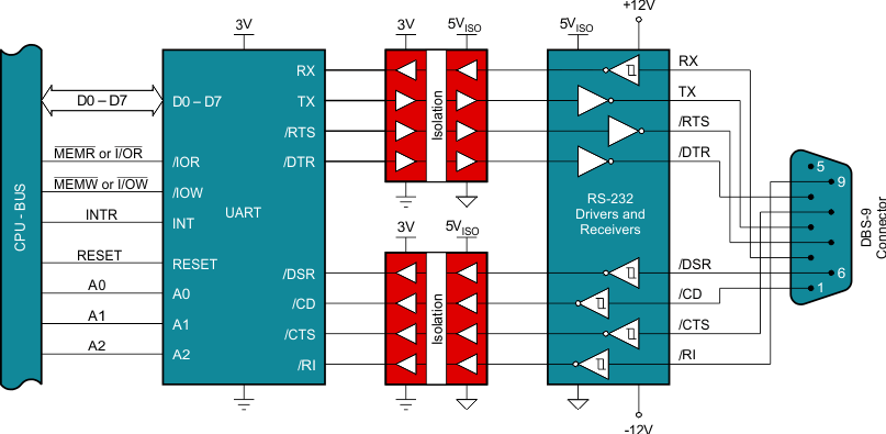
The full-blown, isolated RS-232 interface in Figure 2-3 requires two quad isolators due to the six control signals required in addition to the actual data lines, RX and TX. Although the entire system is single-ended, the high-voltage requirements of the symmetric, 13-V bus supply make it necessary to galvanically isolate the data link between the UART and the low-voltage side of the bus transceiver. Also, the 13-V dc bus may be in turn generated from a higher supply, in which case the isolation also serves as a means of protection against high-voltage transients on the system supply lines.
 Figure 2-3 Isolated RS-232 Interface
As in the example in Figure 2-3, the isolation of the RS-485 interface in Figure 2-4 occurs between the controller and the bus transceiver. Despite the entire interface circuit being a low-volt system, the differential nature of the transmission bus requires prior isolation on the single-ended side. In a multi-node distributed RS-485 network, different nodes may be referenced to grounds at different potential, in which case isolation enables communication by level shifting between those ground potentials.
 Figure 2-4 Isolated RS-485 Interface
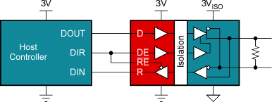
Due to the simplicity of the interface shown in Figure 2-5, it is possible to integrate the isolator function into the transceiver circuit, thus providing an application-specific isolator device featuring low-cost and low component count. Figure 2-5 is an example of an isolated function. For diagrams of how to implement these RS-485 solutions, read How to isolate signal and power for an RS-485 system.
 Figure 2-5 Integrated Isolated RS-485 Interface
Not all applications of digital isolators and isolated functions are covered here. These are just examples to understand how the isolator is placed in a system. For more examples, detailed application diagrams, and use cases, please refer the respective product data sheets.