SLLA284G July 2022 – September 2023 ISO5451 , ISO5452 , ISO5851 , ISO5852S , ISO7142CC , ISO7142CC-Q1 , ISO721 , ISO721-Q1 , ISO721M , ISO721M-EP , ISO722 , ISO7220A , ISO7220M , ISO7221A , ISO7221B , ISO7221C , ISO7221M , ISO722M , ISO7230C , ISO7230M , ISO7231C , ISO7231M , ISO7240C , ISO7240CF , ISO7240M , ISO7241C , ISO7241M , ISO7242C , ISO7242M , ISO7310-Q1 , ISO7310C , ISO7340-Q1 , ISO7340C , ISO7340FC , ISO7341-Q1 , ISO7341C , ISO7341FC , ISO7342-Q1 , ISO7342C , ISO7342FC , ISO7740 , ISO7741 , ISO7742 , ISO7760 , ISO7761 , ISO7762 , ISO7810 , ISO7820 , ISO7821 , ISO7830 , ISO7831 , ISO7840 , ISO7841 , ISO7842
4.8 Decoupling Capacitors
Decoupling capacitors provide a local source of charge for ICs requiring a significant amount of supply current in response to internal switching. Insufficient decoupling causes a lack of supply current required which may prevent the IC from working properly, resulting in signal integrity data errors to occur. This requires them to provide low impedance across the frequency range of interest. To accomplish that, a common approach is to distribute an array of decoupling capacitors evenly across the board. In addition to maintaining signal integrity, decoupling capacitors serve as EMC filters preventing high-frequency RF signals from propagating throughout the PCB.
When connecting a capacitor between the power and ground planes, the power supply is actually loaded with a series resonant circuit, whose frequency dependent R-L-C components represent the equivalent circuit of a real capacitor. Figure 4-15 shows the parasitic components of an initial equivalent circuit and their conversion into a series resonant circuit.
 Figure 4-15 Capacitor Losses Modeled by a Series Resonance Circuit
The leakage resistance RL represents the loss through leakage current at low frequencies. RD and CD indicate the losses due to molecular polarization, (RD), and dielectric absorption, (CD). RS depicts the resistance in the leads and the plates of the capacitor. The three resistive losses are combined into one equivalent series resistance (ESR). As in the ESR case, the equivalent series inductance (ESL) combines the inductance of the capacitor plates and the internal leads.
Note that the capacitor connecting vias, although low in impedance, contribute a significant amount to the series inductance. Therefore, reduce via inductance by using two vias per capacitor terminal.
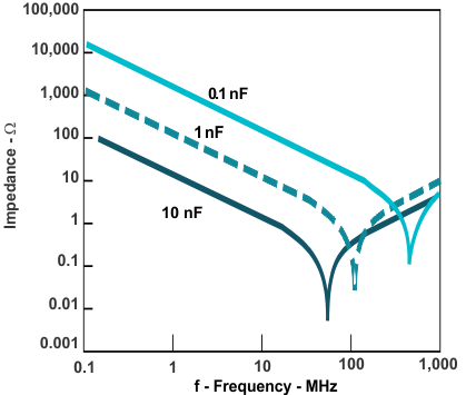
Figure 4-16 shows the progression of capacitor impedance (Z) versus frequency for a 10-nF capacitor. At frequencies far below the self-resonance frequency (SRF), the capacitive reactance is dominant. Closer to SRF, the inductive reactance gains influence trying to neutralize the capacitive component. At SRF, the capacitive and inductive reactance cancel, and only the ESR is effective. Note that the ESR is frequency dependent, and contrary to popular belief, does not reach its minimum at SRF. The impedance Z, however, does.
 Figure 4-16 Capacitor Impedance Versus Frequency
The reason why the paralleling of capacitors in a distributed decoupling network works is because the total capacitance increases to CTOT = C × n, where n is the number of decoupling capacitors used. And with Xc = 1/(ω × C), the capacitor impedance is reduced to Xc = 1/(n × ω × C) for frequencies below SRF. Similarly, this holds true for the inductance. Here LTOT = L/n, and because XL = ω × L, the impedance decreases to XL = ω × L/n for frequencies above SRF.
Designing a solid decoupling network must include lower frequencies down to dc, which requires the implementation of large bypass capacitors. Therefore, to provide sufficient low impedance at low frequencies, place 1-μF to 10-μF tantalum capacitors at the output of voltage regulators and at the point where power is supplied to the PCB. For the higher frequency range, place several 0.1-μF or 0.01-μF ceramic capacitors next to every high-speed switching IC.