SLUUB65B May 2015 – December 2022
- Read This First
- 1 Introduction
- 2 Basic Measurement System
- 3 Device Power Modes
- 4 Device Configuration Registers
- 5 System Control Function
-
6 Impedance Track Fuel Gauging
- 6.1 Introduction
- 6.2 Gauge FW Operation Modes
- 6.3 Current/Power Profiles
- 6.4 Qmax Update
- 6.5 Fast Qmax Update
- 6.6 Resistance Update
- 6.7 Fast Resistance Scaling
- 6.8 StateOfCharge() Smoothing
- 6.9 Additional Impedance Track Gauging Features
- 7 Charging Features
- 8 Lifetime Data Logging Features
- 9 Authentication
- 10Communications
- 11Manufacturer Information
- 12Manufacturer Data
- 13Integrity Data or Checksum
- 14Calibration
-
15Data Commands
- 15.1
Standard Data Commands
- 15.1.1
Control(): 0x00 and 0x01
- 15.1.1.1 CONTROL_STATUS: 0x0000
- 15.1.1.2 DEVICE_TYPE: 0x0001
- 15.1.1.3 FW_VERSION: 0x0002
- 15.1.1.4 HW_VERSION: 0x0003
- 15.1.1.5 RESET_DATA: 0x0005
- 15.1.1.6 PREV_MACWRITE: 0x0007
- 15.1.1.7 CHEM_ID: 0x0008
- 15.1.1.8 BOARD_OFFSET: 0x0009
- 15.1.1.9 CC_OFFSET: 0x000A
- 15.1.1.10 DF_VERSION: 0x000C
- 15.1.1.11 SET_FULLSLEEP: 0x0010
- 15.1.1.12 SET_HIBERNATE: 0x0011
- 15.1.1.13 CLEAR_HIBERNATE: 0x0012
- 15.1.1.14 SET_SHUTDOWN: 0x0013
- 15.1.1.15 CLEAR_SHUTDOWN: 0x0014
- 15.1.1.16 SET_HDQINTEN: 0x0015
- 15.1.1.17 CLEAR_HDQINTEN: 0x0016
- 15.1.1.18 STATIC_CHEM_CHKSUM: 0x0017
- 15.1.1.19 ALL_DF_CHKSUM: 0x0018
- 15.1.1.20 STATIC_DF_CHKSUM: 0x0019
- 15.1.1.21 SYNC_SMOOTH: 0x001E
- 15.1.1.22 SEALED: 0x0020
- 15.1.1.23 IT ENABLE: 0x0021
- 15.1.1.24 IMAX_INT_CLEAR: 0x0023
- 15.1.1.25 CAL_ENABLE: 0x002D
- 15.1.1.26 RESET: 0x0041
- 15.1.1.27 EXIT_CAL: 0x0080
- 15.1.1.28 ENTER_CAL: 0x0081
- 15.1.1.29 OFFSET_CAL: 0x0082
- 15.1.2 AtRate(): 0x02 and 0x03
- 15.1.3 UnfilteredSOC(): 0x04 and 0x05
- 15.1.4 Temperature(): 0x06 and 0x07
- 15.1.5 Voltage(): 0x08 and 0x09
- 15.1.6 Flags(): 0x0A and 0x0B
- 15.1.7 NomAvailableCapacity(): 0x0C and 0x0D
- 15.1.8 FullAvailableCapacity(): 0x0E and 0x0F
- 15.1.9 RemainingCapacity(): 0x10 and 0x11
- 15.1.10 FullChargeCapacity(): 0x12 and 0x13
- 15.1.11 AverageCurrent(): 0x14 and 0x15
- 15.1.12 TimeToEmpty(): 0x16 and 0x17
- 15.1.13 FilteredFCC(): 0x18 and 0x19
- 15.1.14 SafetyStatus(): 0x1A and 0x1B
- 15.1.15 UnfilteredFCC(): 0x1C and 0x1D
- 15.1.16 Imax(): 0x1E and 0x1F
- 15.1.17 UnfilteredRM(): 0x20 and 0x21
- 15.1.18 FilteredRM(): 0x22 and 0x23
- 15.1.19 BTPSOC1Set(): 0x24 and 0x25
- 15.1.20 BTPSOC1Clear(): 0x26 and 0x27
- 15.1.21 InternalTemperature(): 0x28 and 0x29
- 15.1.22 CycleCount(): 0x2A and 0x2B
- 15.1.23 StateOfCharge(): 0x2C and 0x2D
- 15.1.24 StateOfHealth(): 0x2E and 0x2F
- 15.1.25 ChargingVoltage(): 0x30 and 0x31
- 15.1.26 ChargingCurrent(): 0x32 and 0x33
- 15.1.27 PassedCharge(): 0x34 and 0x35
- 15.1.28 DOD0(): 0x36 and 0x37
- 15.1.29 SelfDischargeCurrent(): 0x38 and 0x39
- 15.1.1
Control(): 0x00 and 0x01
- 15.2
Extended Data Commands
- 15.2.1 PackConfiguration(): 0x3A and 0x3B
- 15.2.2 DesignCapacity(): 0x3C and 0x3D
- 15.2.3 DataFlashClass(): 0x3E
- 15.2.4 DataFlashBlock(): 0x3F
- 15.2.5 BlockData(): 0x40 Through 0x5F
- 15.2.6 BlockDataCheckSum(): 0x60
- 15.2.7 BlockDataControl(): 0x61
- 15.2.8 DODatEOC(): 0x62 and 0x63
- 15.2.9 Qstart(): 0x64 and 0x65
- 15.2.10 FastQmax(): 0x66 and 0x67
- 15.2.11 Reserved—0x68 to 0x6C
- 15.2.12 Reserved—0x6E and 0x6F
- 15.2.13 Reserved—0x70 and 0x71
- 15.2.14 Reserved—0x72 and 0x73
- 15.2.15 AveragePower(): 0x76 and 0x77
- 15.2.16 AN_COUNTER: 0x79
- 15.2.17 AN_CURRENT_LSB: 0x7A
- 15.2.18 AN_CURRENT_MSB: 0x7B
- 15.2.19 AN_VCELL_LSB: 0x7C
- 15.2.20 AN_VCELL_MSB: 0x7D
- 15.2.21 AN_TEMP_LSB: 0x7E
- 15.2.22 AN_TEMP_MSB: 0x7F
- 15.1
Standard Data Commands
- 16Data Flash Summary
- 17Factory Calibration
- 18Updating the BQ27542-G1 Firmware
- 19Impedance Track Gauge Configuration
- 20Revision History
5.7 Battery Trip Point Interrupt Function
To provide increased flexibility for capacity-based interrupts to the host, the fuel gauge incorporates a Battery Trip Point (BTP) function that allows the system to dynamically update the traditional SOC1 Set Threshold and SOC1 Clear Threshold at runtime using the BTPSOC1Set() and BTPSOC1Clear() standard commands. These thresholds are used to trigger an interrupt on the HDQ pin whenever the set or clear thresholds are crossed following an update to the BTPSOC1Set() and BTPSOC1Clear() values. Configuration of the interrupt polarity and enable/disable of the feature is provided via the Pack Configuration [INTPOL] and Pack Configuration C [BTP_EN] bits, respectively, while initialization values for the interrupt set and clear thresholds are programmed in SOC1 Set Threshold and SOC1 Clear Threshold as normal.
Enabling of the BTP feature automatically disables all other interrupt sources on the HDQ pin, so care must be taken in configuring the fuel gauge for each particular end application, especially if non-BTP interrupts such as overtemperature, internal short detection, Tab Disconnect Detection, and battery low and high indications are required in the system.
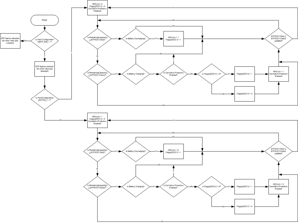
When BTP is enabled, the fuel gauge continuously compares RemainingCapacity() with the values programmed in BTPSOC1Set() and BTPSOC1Clear() to determine whether or not it has crossed below the set or above the clear threshold. Once a threshold is crossed, additional conditions are verified to guard against an unintended interrupt trigger. For the BTP set threshold, the direction of current flow is checked to confirm that a discharge event is occurring. If true, the Flags()[SOC1] bit is set to 1 and an interrupt asserts on the HDQ pin. For the BTP clear threshold, the device again checks the direction of current flow to ensure that a charge event is occurring. Afterwards, an internal variable is examined to determine whether or not a change in the state of Flags()[SOC1] has already occurred due to a prior clear threshold crossing. If true, no change is made and a new interrupt will not fire; however, it is implied that a pre-existing interrupt will still be asserted. If false, the current state of Flags()[SOC1] is flipped to its opposite value and an interrupt subsequently triggered on the HDQ pin. In this way, the correct behavior is guaranteed in cases where the host updates the BTP set and clear thresholds diligently based on HDQ interrupts, but also when there is a failure to update the thresholds. If, at any time, new values are written to either BTPSOC1Set() or BTPSOC1Clear(), then the [SOC1] flag automatically reinitializes to 0 and the HDQ pin de-asserts to its default state. The entire functional flow of the BTP feature is illustrated in Figure 6-1, BTP Algorithm Flow.
 Figure 5-1 BTP Algorithm Flow
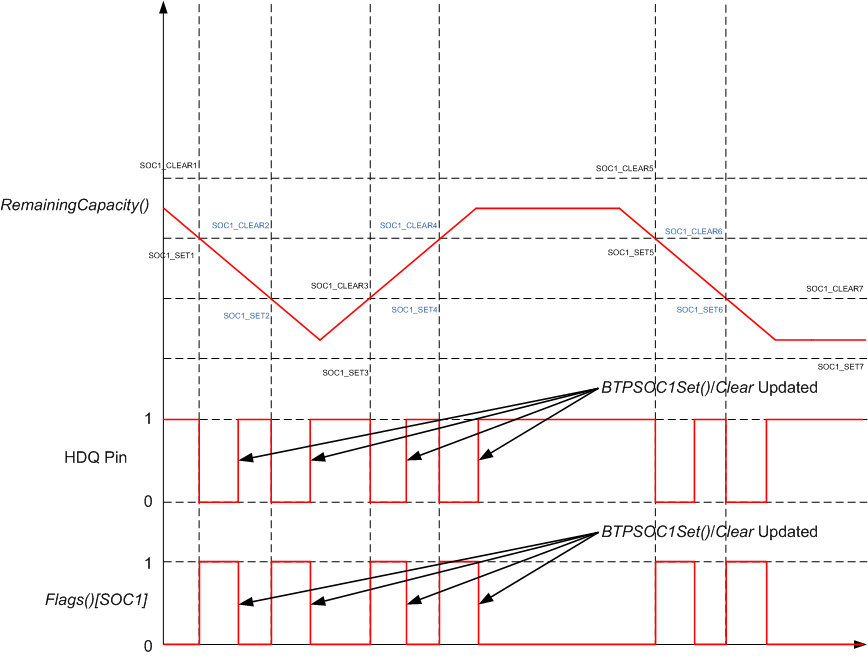
In normal usage, the BTP thresholds are continuously updated by the host system at predetermined increments, each time reinitializing the Flags()[SOC1] bit to 0 and waiting for the crossing of the next threshold to trigger a new interrupt. If the thresholds are always updated after each interrupt, then it is implied that the crossing of a set or clear threshold always triggers a new interrupt. This is highlighted below in Figure 6-2, BTP Configuration with Multiple Thresholds.
 Figure 5-2 BTP Configuration with Multiple Thresholds
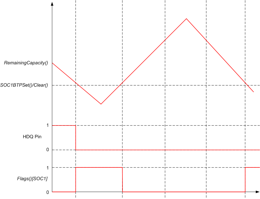
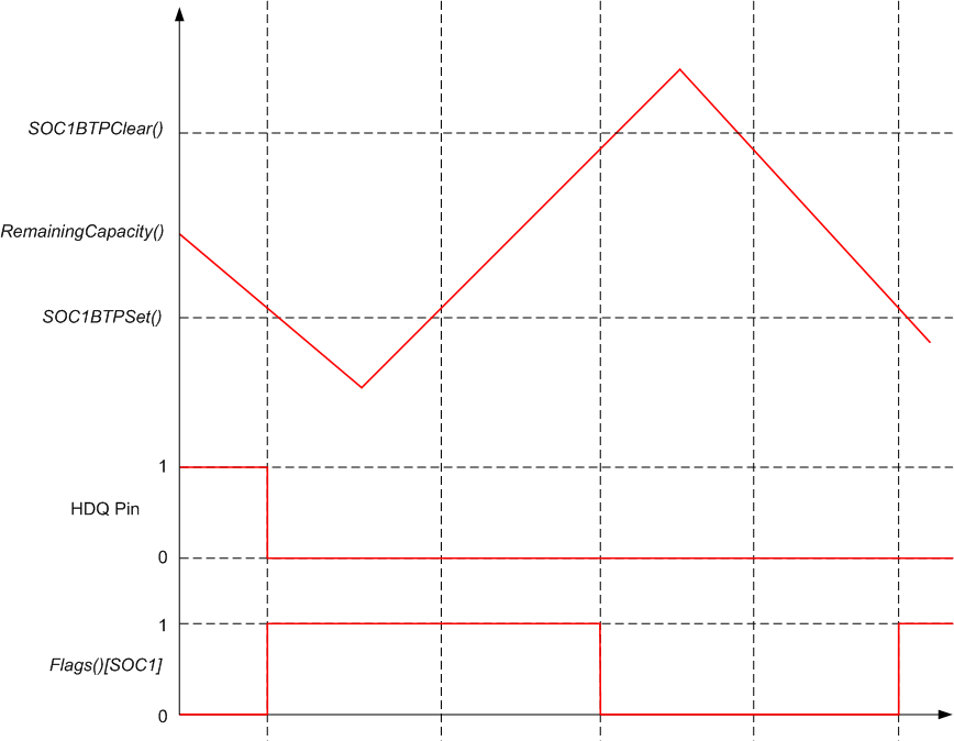
However, it is possible that the host may fail to write new thresholds or experience a significant delay in attempting to do so. In this case, there could be an occurrence where the clear threshold is crossed after an interrupt due to a prior set threshold crossing. Thus, the [SOC1] bit would experience a change but a new interrupt would not be triggered on HDQ. Thus, continued crossings without updates to BTPSOC1Set() or BTPSOC1Clear() will only result in changes to Flags()[SOC1]. Figure 6-3, BTP Configuration with Shared Thresholds, shows the case where identical thresholds are written to BTPSOC1Set() or BTPSOC1Clear(). Figure 6-4, BTP Configuration with Separate Thresholds, shows the alternate case where unique thresholds are written to BTPSOC1Set() or BTPSOC1Clear().
 Figure 5-3 BTP Configuration with Shared Thresholds
 Figure 5-4 BTP Configuration with Separate Thresholds