SCAA126C June 2022 – July 2022 SN3257-Q1 , SN74CBTU4411 , TMUX1072 , TMUX1104 , TMUX1108 , TMUX1111 , TMUX1119 , TMUX1204 , TMUX1208 , TMUX1219 , TMUX1308 , TMUX1308-Q1 , TMUX1308A-Q1 , TMUX136 , TMUX1511 , TMUX154E , TMUX1574 , TMUX1575 , TMUX4051 , TMUX4052 , TMUX4053 , TS3A24157 , TS3A24159 , TS3A27518E , TS3A44159 , TS3A4741 , TS3A4742 , TS3A4751 , TS3A5018 , TS3A5223 , TS5A12301E , TS5A21366 , TS5A22362 , TS5A22364 , TS5A22364-Q1 , TS5A22366 , TS5A23167 , TS5MP645 , TS5MP646
1 Application Brief
A common need of any system is controlling multiple devices through digital logic. Systems continue to move to lower voltage nodes for power savings. With this trend, using devices that are not natively compatible with the control logic of the system can lead to extra system costs through board size and BOM count. Also, the use of more components in the design of the system creates more opportunities for power sequencing issues. Using devices that have integrated support for the control logic of the system achieves a cost effective solution.
To prevent digital logic control issues, the system must ensure that the output high (VOH) logic output is higher than the input high (VIH) logic input it is controlling. In addition, the output low (VOL) of the logic output must be lower than the input low (VIL) of the logic input it is controlling. See Figure 1-1 for this logic standard. Some components may not meet the standard, but having VIH < VOH and VIL > VOL ensures proper system operation.
 Figure 1-1 Logic Thresholds
If a processor on a 1.8-V voltage rail is controlling a signal switch with a supply rail of 3.3 V without integrated 1.8-V logic capability, the system is required to use an external translator as shown in Figure 1-2 or a translator. The voltage domain translation is necessary because the VIH for a 3.3-V device is higher than the VOH of a 1.8-V processor that is controlling the device.
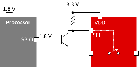 Figure 1-2 Discrete BJT Translator
Example Application
In Figure 1-3, an 8 to 1 MUX expands the sensors being sampled by an ADC. Without 1.8-V logic, a 12 pin (4 bit) translator is required in between the processor and the MUX. By adding a 4 bit translator to an 8:1 MUX the board area for the MUX is increased by more than 25%.
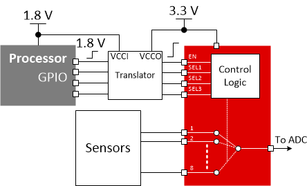 Figure 1-3 8:1 MUX Without 1.8-V Logic
By choosing a device with integrated 1.8-V logic, the discrete components can be removed, see Figure 1-4. This leads to a direct connection of the logic control from the processor to the device even with a supply domain mismatch. Not only does this remove component cost and board space, any supply sequencing requirements associated with the translator are also removed from the system operation requirements.
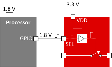 Figure 1-4 MUX or Switch With Integrated 1.8-V Logic
Different Forms of 1.8-V Logic and Their Trade-Offs
With 1.8-V logic there are different implementations with their own benefits and drawbacks. When the input to a typical CMOS logic buffer is not at the supply rail, a shoot through current can be observed from the device supply to ground. This is due to both transistors being partially on creating a path to ground, with an increase in ICC as shown in Figure 1-5. An example device is the TS5A2066 that has an input thresholds of 70% of VCC for VIH and 30% of VCC for VIL and is not 1.8-V compatible logic.
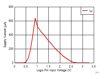 Figure 1-5 70% or 30% Threshold ICC vs. Logic
Input Voltage
Figure 1-5 70% or 30% Threshold ICC vs. Logic
Input Voltage1.8-V Compatible Logic Inputs
With the proper implementation, 1.8-V compatible inputs can be achieved while minimizing the shoot through current observed in a standard CMOS buffer input. In Figure 1-6, the shoot through current is remains low compared to the TS5A2066 while still operating from a 3.3-V supply. When the input voltage is at the supply rails, the ICC is minimal. With this approach the external translator is no longer needed and the lowICC is maintained.
 Figure 1-6 1.8-V Compatible ICC vs Logic Input Voltage
Fixed Logic Thresholds
The TMUX136 is a high-speed 2:1 MUX that supports fixed thresholds across the supply range for 1.8-V logic inputs. This method has little to no change in ICC with change in logic input voltage as shown in Figure 1-7. The static current consumption with this device will be higher as a trade-off.
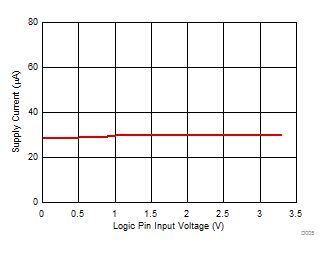 Figure 1-7 Fixed Threshold ICC vs Logic Input Voltage
Logic Supply Input Pin
Another approach is to use the TS5A26542 with an input logic supply pin (VIO) to set the desired voltage of the input logic. Because the logic buffer is supplied by a rail that matches the input voltage, there is no shoot through current from the VCC pin as shown in Figure 1-8 even with a 3.3-V supply (The ICC for this measurement is in the 10- to 20-nA range). There is a small shoot through current from the logic supply pin, but it is minimal. The trade-off is an extra pin is required to achieve this functionality.
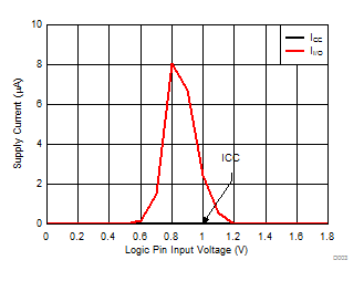 Figure 1-8 Separate Logic Supply Pin ICC vs.
Logic Input Voltage
Figure 1-8 Separate Logic Supply Pin ICC vs.
Logic Input VoltageTable 1-1 lists the alternative device recommendations.
| Device | Configuration | Key Features |
|---|---|---|
| TMUX1574 | 4-channel 2:1 | Powered-off protection, low CON (7.5 pF), low RON (2 Ω), wide bandwidth (2 GHz), 1.8-V compatible logic |
| TMUX1575 | 4-channel 2:1 | 1.3 mm × 1.3 mm package, 1.2-V compatible control inputs, powered-off protection, low CON (10 pF), low RON (1.7 Ω), 1.8-GHz bandwidth |
| TMUX1511 | 4-channel 1:1 | Powered-off protection, low CON (3.3 pF), low RON (2 Ω), wide bandwidth (3 GHz), 1.8-V compatible logic |
| TS3A27518E | 6-channel 2:1 | Powered-off protection, 1.8-V compatible control inputs |
| TMUX1308 | 1-channel 8:1 | 1.8-V compatible control inputs, injection current control |
| TMUX4051 | 1-channel 8:1 | ±12-V signal range, 1.8-V compatible logic |
| TMUX4052 | 2-channel 4:1 | ±12-V signal range, 1.8-V compatible logic |
| TMUX4053 | 3-channel 2:1 | ±12-V signal range, 1.8-V compatible logic |