SPRUIX0D February 2021 – August 2021
- Trademarks
- 1Introduction
- 2Important Usage Notes
-
3System Description
- 3.1 Key Features
- 3.2 Functional Block Diagram
- 3.3 Power-On/Off Procedures
- 3.4
Peripheral and Major Component
Description
- 3.4.1 Clocking
- 3.4.2 Reset
- 3.4.3 Power
- 3.4.4 Configuration
- 3.4.5 JTAG
- 3.4.6 Test Automation
- 3.4.7 UART Interfaces
- 3.4.8 Memory Interfaces
- 3.4.9 Ethernet Interface
- 3.4.10 Display Interface
- 3.4.11 USB 2.0 Interface
- 3.4.12 PCIe Interface
- 3.4.13 High Speed Expansion Interface
- 3.4.14 CAN Interface
- 3.4.15 Interrupt
- 3.4.16 ADC Interface
- 3.4.17 Safety Connector
- 3.4.18 SPI Interfaces
- 3.4.19 I2C Interfaces
- 3.4.20 FSI Interface
- 4Known Issues and Modifications
- 5References
- 6Revision History
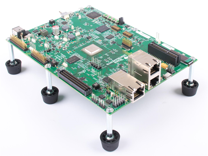
1 Introduction
The AM64x/AM243x GP EVM is a standalone test, development, and evaluation module (EVM) that lets developers evaluate the AM64x/AM243x functionality and develop prototypes for a variety of applications. The EVM implements either the Sitara™ AM6442 MPU or the AM2434 MCU. Additional supporting components allow the user to make use of the various device interfaces including Industrial Ethernet, standard Ethernet, PCIe, Fast Serial Interface (FSI) and others to easily create prototypes. An on-board display makes use of AM64x/AM243x serial peripheral interface (SPI) ports to provide the ability for local visual outputs in addition to the various LED provided. On-board current measurement capabilities are available to monitor power consumption for power-conscious applications. The supplied USB cable paired with embedded emulation logic allows for emulation and debugging using standard development tools such as Code Composer Studio™ software from TI.