SLUUDO2 September 2026 AM2611 , AM2612 , AM2612-Q1 , AM2631 , AM2631-Q1 , AM2632 , AM2632-Q1 , AM2634 , AM2634-Q1 , AM263P2 , AM263P2-Q1 , AM263P4 , AM263P4-Q1
- 1
- Abstract
- Trademarks
- 1Acronyms
- 2Introduction
- 3Introduction to CPSWSS and ENET-LLD
-
4Debugging Hardware and Software
- 4.1 Hardware Debugging
- 4.2 Custom Hardware Bring-Up Process
- 4.3 Debugging Packet Forwarding Issues (ALE and Statistics)
- 4.4 Custom Board Enablement in SYSCFG
- 4.5 LwIP Debug Guide
- 5Conclusion
- 6References
4.1.2.4 Mode Settings
Master and slave mode determines which device provides the master clock for the physical layer connection.
- Master PHY uses the internal local oscillator to generate the transmit clock.
- Slave PHY locks onto the incoming signal from the master using a phase-locked loop (PLL) and recovers the clock to synchronize the individual transmissions.
In gigabit Ethernet, one end of the link must act as master (transmits the clock) and the other as slave (receives and locks to the clock). This configuration can be established through different means.
- Hardware Strapping or Register Bit Settings: The user can manually force a device to act exclusively as a master or a slave. This is common in automotive Ethernet (like 100BASE-T1) or fixed infrastructure. Basically, if the speed and duplexity is forced then this configuration must be enabled in hardware.
- Auto-Negotiation Resolution: By default, devices use a priority hierarchy to make decisions. For example, a multiport switch typically takes priority as the master over a single-port network interface card (NIC). If two identical devices connect, these devices use a random seed generator to determine which is the master.
From a SW perspective, this configuration can be done through a SYSCFG extended PHY configuration. For example, the DP83TG721 PHY has this feature of configuring master or slave mode using an extended configuration. The same PHY also has the provision to configure the master or slave mode using HW strapping. More details on these configurations are available in the specific datasheet for the PHYs. The configuration made using the extended configuration is used to set the PMA_CTRL register.
In case you are using a media convertor, the media convertor EVM also has a master or slave jumper which must be set correctly. An example is shown in Figure 4-5 for the DP83TG720/TG721 evaluation module for a 1Gbps media convertor.
 Figure 4-5 PHY Jumper Configuration
Figure 4-6 shows an example for configuring an MDI master or slave configuration using SYSCFG.
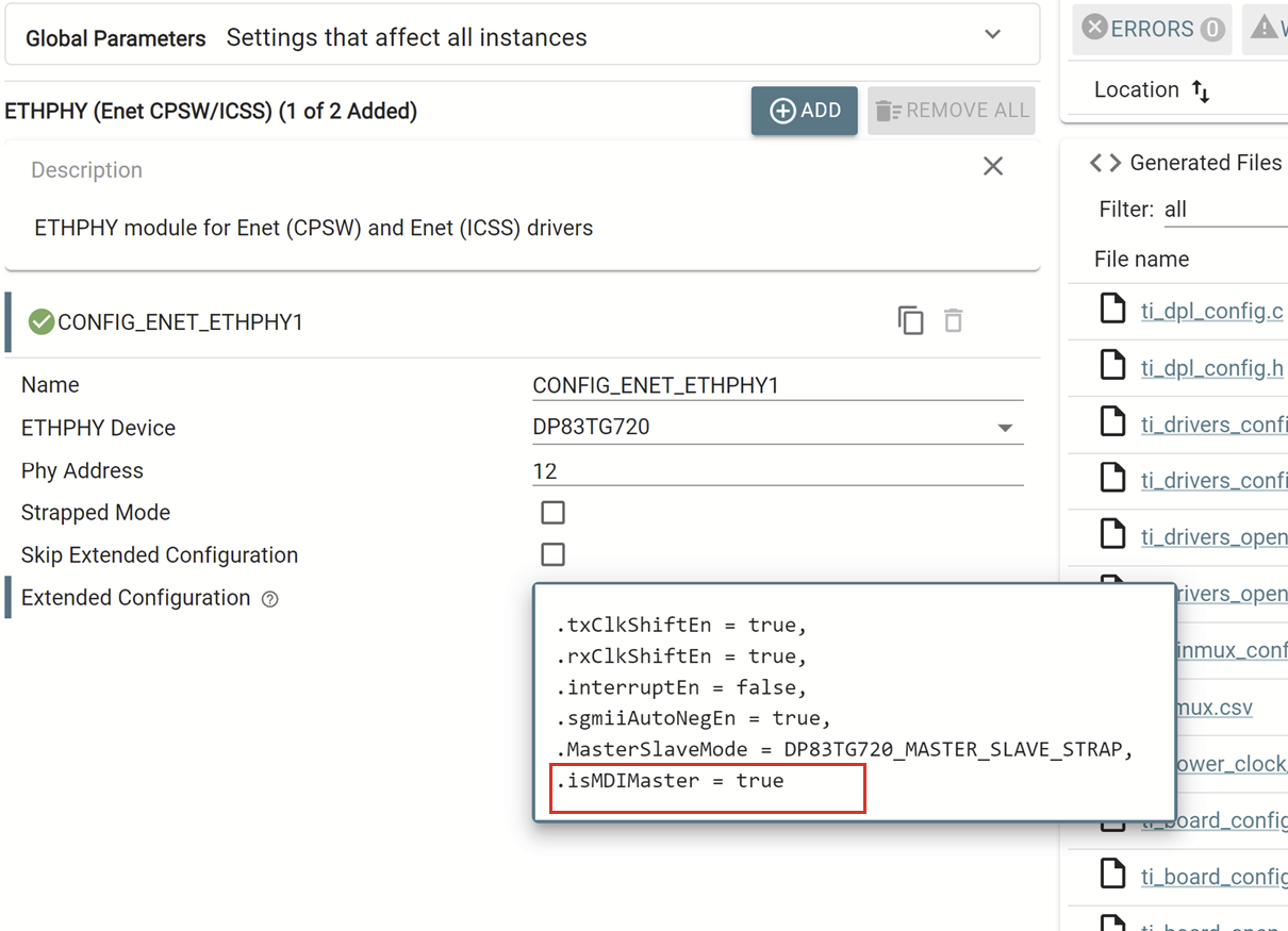 Figure 4-6 SYSCFG Setting for MDI
Master
Figure 4-6 SYSCFG Setting for MDI
Master