SLPA020 May 2022 CSD13201W10 , CSD13202Q2 , CSD13302W , CSD13303W1015 , CSD13306W , CSD13380F3 , CSD13381F4 , CSD13383F4 , CSD13385F5 , CSD15380F3 , CSD15571Q2 , CSD16301Q2 , CSD16321Q5 , CSD16322Q5 , CSD16323Q3 , CSD16325Q5 , CSD16327Q3 , CSD16340Q3 , CSD16342Q5A , CSD16401Q5 , CSD16403Q5A , CSD16404Q5A , CSD16406Q3 , CSD16407Q5 , CSD16408Q5 , CSD16409Q3 , CSD16410Q5A , CSD16411Q3 , CSD16412Q5A , CSD16413Q5A , CSD16414Q5 , CSD16415Q5 , CSD16556Q5B , CSD16570Q5B , CSD17301Q5A , CSD17302Q5A , CSD17303Q5 , CSD17304Q3 , CSD17305Q5A , CSD17306Q5A , CSD17307Q5A , CSD17308Q3 , CSD17309Q3 , CSD17310Q5A , CSD17311Q5 , CSD17312Q5 , CSD17313Q2 , CSD17318Q2 , CSD17322Q5A , CSD17327Q5A , CSD17381F4 , CSD17382F4 , CSD17483F4 , CSD17484F4 , CSD17501Q5A , CSD17505Q5A , CSD17506Q5A , CSD17507Q5A , CSD17510Q5A , CSD17522Q5A , CSD17527Q5A , CSD17551Q3A , CSD17551Q5A , CSD17552Q3A , CSD17552Q5A , CSD17553Q5A , CSD17555Q5A , CSD17556Q5B , CSD17559Q5 , CSD17570Q5B , CSD17571Q2 , CSD17573Q5B , CSD17575Q3 , CSD17576Q5B , CSD17577Q3A , CSD17577Q5A , CSD17578Q3A , CSD17578Q5A , CSD17579Q3A , CSD17579Q5A , CSD17581Q3A , CSD17581Q5A , CSD17585F5 , CSD18501Q5A , CSD18502KCS , CSD18502Q5B , CSD18503KCS , CSD18503Q5A , CSD18504KCS , CSD18504Q5A , CSD18509Q5B , CSD18510KCS , CSD18510KTT , CSD18510Q5B , CSD18511KCS , CSD18511KTT , CSD18511Q5A , CSD18512Q5B , CSD18513Q5A , CSD18514Q5A , CSD18531Q5A , CSD18532KCS , CSD18532NQ5B , CSD18532Q5B , CSD18533KCS , CSD18533Q5A , CSD18534KCS , CSD18534Q5A , CSD18535KCS , CSD18535KTT , CSD18536KCS , CSD18536KTT , CSD18537NKCS , CSD18537NQ5A , CSD18540Q5B , CSD18541F5 , CSD18542KCS , CSD18542KTT , CSD18543Q3A , CSD18563Q5A , CSD19501KCS , CSD19502Q5B , CSD19503KCS , CSD19505KCS , CSD19505KTT , CSD19506KCS , CSD19506KTT , CSD19531KCS , CSD19531Q5A , CSD19532KTT , CSD19532Q5B , CSD19533KCS , CSD19533Q5A , CSD19534KCS , CSD19534Q5A , CSD19535KCS , CSD19535KTT , CSD19536KCS , CSD19536KTT , CSD19537Q3 , CSD19538Q2 , CSD19538Q3A , CSD22202W15 , CSD22204W , CSD22205L , CSD22206W , CSD23202W10 , CSD23203W , CSD23280F3 , CSD23285F5 , CSD23381F4 , CSD23382F4 , CSD25202W15 , CSD25211W1015 , CSD25213W10 , CSD25304W1015 , CSD25310Q2 , CSD25402Q3A , CSD25404Q3 , CSD25480F3 , CSD25481F4 , CSD25483F4 , CSD25484F4 , CSD25485F5 , CSD25501F3 , CSD75207W15 , CSD75208W1015 , CSD83325L , CSD85301Q2 , CSD85302L , CSD85312Q3E , CSD86311W1723 , CSD86330Q3D , CSD86336Q3D , CSD86350Q5D , CSD86356Q5D , CSD86360Q5D , CSD87312Q3E , CSD87313DMS , CSD87330Q3D , CSD87331Q3D , CSD87333Q3D , CSD87334Q3D , CSD87335Q3D , CSD87350Q5D , CSD87351Q5D , CSD87351ZQ5D , CSD87352Q5D , CSD87353Q5D , CSD87355Q5D , CSD87381P , CSD87384M , CSD87501L , CSD87502Q2 , CSD87503Q3E , CSD87588N , CSD88537ND , CSD88539ND , CSD88584Q5DC , CSD88599Q5DC
1 Application Brief
Paralleling power metal-oxide semiconductor field-effect transistors (MOSFETs) is a common way to reduce conduction losses and spread power dissipation over multiple devices to limit the maximum junction temperature. This application brief shares best practices and examples of paralleling power MOSFETs in various applications.
First, consider static operation with two FETs operating in parallel, as shown in Figure 1-2.
The current in each FET is proportional to the inverse of its on resistance, RDS(on). Naturally, the device with the lowest RDS(on) will carry more current. As it heats up, its RDS(on) increases, shifting some of the current to the other FETs. The junction temperatures of paralleled FETs with good thermal coupling will be roughly the same. Current sharing still depends on the relative on-resistance of each FET and will be within the RDS(on) tolerances specified in the MOSFET data sheet.
During dynamic operation, the FET with the lowest threshold voltage, VGS(th), turns on first and turns off last. This FET takes more of the switching losses and sees higher stresses during switching transitions. To some extent, the thermal sharing effect balances out the switching and conduction losses, and the FETs will operate at roughly the same temperature.
Best Practices When Paralleling Power MOSFETs
Here are helpful tips when using FETs in parallel:
- Each FET needs its own gate resistor with a value from a few ohms up to tens of ohms. This helps with current sharing and prevents gate oscillations.
- FETs need good thermal coupling to ensure current and thermal balancing between devices. They can be mounted on a common heat sink or copper plane to maintain equal temperatures.
- The placement and layout of each FET should be identical and symmetrical, within reason, to equalize parasitic inductance in the critical gate-to-source and drain-to-source loops.
- Ensure that the gate-drive circuit can drive the higher capacitance (charge) of multiple devices without getting too hot. Remember, capacitance (charge) is multiplied by the number of paralleled MOSFETs.
- Avoid adding external capacitors from gate-to-source or gate-to-drain. If necessary, adjust the gate resistor’s value to optimize the switching speed of the FETs .
- If you need Zener diodes to protect the MOSFET driver, place them close to the gate-driver outputs and before the gate resistors.
Schematic and PCB Layout Examples
Figure 1-3 shows a partial schematic and picture of the TPS2482 hot-swap evaluation module (EVM).
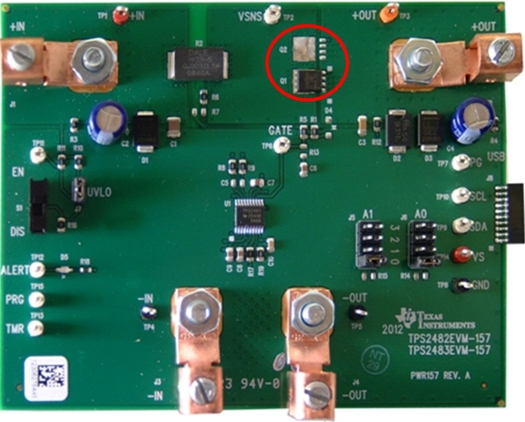 |
As you can see in Figure 1-4, the TPS2482 EVM uses two CSD18501Q5A MOSFETs in parallel. The schematic shows how each FET has a 10-Ω gate resistor; the Zener diode is on the gate-driver output before the gate resistors. The FETs are placed close together on the same copper shape and use vias for good thermal coupling to spread the heat.
The next example, shown in Figure 1-4, is from the 18 V/1 kW, 160A Peak, >98% Efficient, High Power Density Brushless Motor Drive Reference Design.
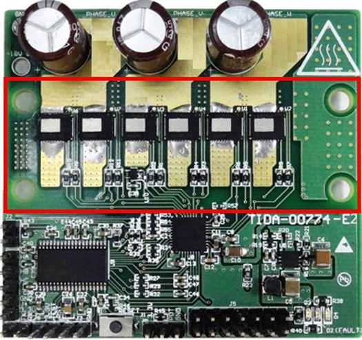 |
This reference design uses two CSD88584Q5DC power MOSFETs in parallel per phase. Attaching the MOSFETs to the same heat sink for good thermal coupling helps remove the heat through the top side of the package. The design includes individual 3.3-Ω gate resistors for each FET in the power block.
The final example, shown in Figure 1-5 is from the 48-VDC Battery Powered 5-kW Inverter Power Stage Reference Design for Forklift AC Traction Motor.
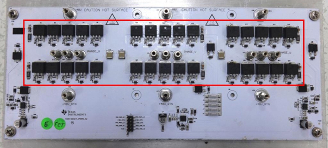 |
This reference design uses five CSD19536KTT power MOSFETs in parallel for the high- and low-side switches in each phase. The FETs are mounted on an insulated metal substrate for cooling and good thermal coupling between devices. Each FET has an 8.2-Ω gate resistor.
Conclusion
Because of their inherent current- and thermal-sharing properties, paralleling MOSFETs can reduce conduction losses and limit their maximum junction temperature. Operating power MOSFETs in parallel can help solve the problems discussed in this article, but at a higher component count and cost, and a larger PCB area. If possible, use a single FET; if you cannot, carefully consider the design and layout of parallel FETs in your application to ensure success.
Additional Resources
Check out the following technical articles: